


1
A
B
C
2
2
3
4
5
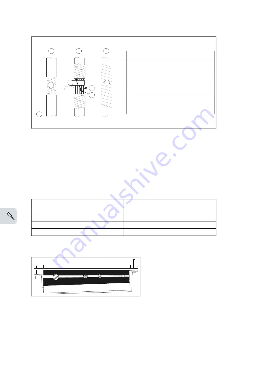
Stripped cable
A
Conductive surface of the shield exposed
B
Stripped part covered with copper foil
C
Cable shield
1
Copper foil
2
Shielded twisted pair
3
Grounding wire
4
Note for top entry of cables:
When each cable has its own rubber grommet, sufficient IP
and EMC protection can be achieved. However, if very many control cables come to one
cabinet, plan the installation beforehand as follows:
1.
Make a list of the cables coming to the cabinet.
2.
Sort the cables going to the left into one group and the cables going to the right into
another group to avoid unnecessary crossing of cables inside the cabinet.
3.
Sort the cables in each group according to size.
4.
Group the cables for each grommet as follows ensuring that each cable has a proper
contact to the cushions on both sides.
Max. number of cables per grommet
Cable diameter in mm
4
≤ 13
3
≤ 17
2
< 25
1
≥ 25
5.
Arrange the bunches according to size from thickest to the thinnest between the EMI
conductive cushions.
Electrical installation 99
5.
Arrange the bunches according to size from thickest to the thinnest between the EMI
conductive cushions.
6.
If more than one cable go through a grommet, seal the grommet by applying Loctite
5221 (catalogue number 25551) inside the grommet.
Routing the control cables inside the cabinet
Use the existing trunking in the cabinet wherever possible. Use sleeving if cables are laid
against sharp edges. When running cables to or from the swing-out frame, leave enough
slack at the hinge to allow the frame to open fully.
Connecting to the inverter control unit (A41)
Connect the conductors to the appropriate terminals (see page
127
) of the control unit or
terminal block X504 (L504).
Connect the inner twisted pair shields and all separate grounding wires to the grounding
clamps below the control unit.
The drawing below represents a drive with additional I/O terminal block (L504).
Without the block, the grounding is made the same way.
Notes:
•
Do not ground the outer shield of the cable here since it is grounded at the lead-
through.
•
Keep any signal wire pairs twisted as close to the terminals as possible. Twisting the
wire with its return wire reduces disturbances caused by inductive coupling.
6.
If more than one cable go through a grommet, seal the grommet by applying Loctite
5221 (catalogue number 25551) inside the grommet.
106 Electrical installation
Summary of Contents for ACS580-07
Page 1: ... ABB GENERAL PURPOSE DRIVES ACS580 07 Hardware manual ...
Page 2: ......
Page 4: ......
Page 14: ...14 ...
Page 21: ...Measuring points of frames R6 to R9 are shown below PE L1 L2 L3 Safety instructions 21 ...
Page 26: ...26 ...
Page 30: ...30 ...
Page 50: ...50 ...
Page 62: ...62 ...
Page 95: ...Electrical installation 95 11 ...
Page 101: ...Electrical installation 101 11 ...
Page 114: ...114 ...
Page 128: ...128 ...
Page 134: ...134 ...
Page 142: ...142 Maintenance ...
Page 155: ...3 4 5 Maintenance 155 ...
Page 157: ...8 Disconnect the drive module output busbars M12 70 N m 52 lbf ft 7 8 Maintenance 157 ...
Page 161: ...4 5 3 Maintenance 161 ...
Page 163: ...8 Disconnect the drive module output busbars M12 70 N m 52 lbf ft 7 8 Maintenance 163 ...
Page 169: ...1 2 3 5a 5b CR2032 Maintenance 169 ...
Page 170: ...170 ...
Page 186: ...Frame R6 Input and motor cable terminal dimensions option F289 DET A 186 Technical data ...
Page 201: ...Frame R9 Input and motor cable terminal dimensions option F289 Technical data 201 ...
Page 202: ...Frame R10 Input and motor cable terminal dimensions bottom entry and exit 202 Technical data ...
Page 204: ...Frame R10 Input and motor cable terminal dimensions top entry and exit 204 Technical data ...
Page 206: ...Frame R11 Input and motor cable terminal dimensions bottom entry and exit 206 Technical data ...
Page 208: ...Frame R11 Input and motor cable terminal dimensions top entry and exit 208 Technical data ...
Page 217: ...Declaration of Conformity Technical data 217 ...
Page 218: ...218 Technical data ...
Page 223: ...Dimension drawings Example dimension drawings are shown below 13 Dimension drawings 223 ...
Page 224: ...Frames R6 and R7 IP21 UL Type 1 224 Dimension drawings ...
Page 225: ...Frames R6 and R7 B054 IP42 UL Type 1 Dimension drawings 225 ...
Page 226: ...Frames R6 and R7 B055 IP54 UL Type 12 226 Dimension drawings ...
Page 227: ...Frames R6 and R7 H351 and H353 top entry and exit Dimension drawings 227 ...
Page 228: ...Frames R6 and R7 F289 228 Dimension drawings ...
Page 229: ...Frames R6 and R7 F289 H351 H353 Dimension drawings 229 ...
Page 230: ...Frames R8 and R9 IP21 230 Dimension drawings ...
Page 231: ...Frames R8 and R9 B054 IP42 UL Type 1 Dimension drawings 231 ...
Page 232: ...Frames R8 and R9 B055 IP54 UL Type 12 232 Dimension drawings ...
Page 233: ...Frames R8 and R9 H351 and H353 top entry and exit Dimension drawings 233 ...
Page 234: ...Frames R8 and R9 F289 234 Dimension drawings ...
Page 235: ...Frames R8 and R9 F289 H351 H353 Dimension drawings 235 ...
Page 236: ...Frames R10 and R11 IP21 236 Dimension drawings ...
Page 237: ...Frames R10 and R11 B054 IP42 UL Type 1 Dimension drawings 237 ...
Page 238: ...Frames R10 and R11 B055 IP54 UL Type 12 238 Dimension drawings ...
Page 239: ...Frames R10 and R11 F289 T Dimension drawings 239 ...
Page 240: ...Frames R10 and R11 H351 H353 240 Dimension drawings ...
Page 241: ...Frames R10 and R11 B054 IP42 UL type 1 H351 H353 T Dimension drawings 241 ...
Page 242: ...Frames R10 and R11 B055 IP54 UL type 12 H351 H353 T 242 Dimension drawings ...
Page 257: ... Declaration of conformity The Safe torque off function 257 ...
Page 269: ...Setting Parameter 1 s 15 09 RO4 OFF delay Optional I O extension modules 269 ...


