Publication No. HRMCP9 Rev. B
Resources 49
6 •
Resources
This chapter describes system resources, such as memory mapping, register set, and
default interrupt request assignments.
6.1 Memory Map
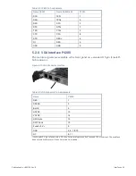
The table below shows the memory address area used by the CR9.
Table 6-1 Memory Area Assignments
Address
Size
Used by
$00000 - $9FFFF
640 KByte
System RAM
$A0000 - $BFFFF
128 KByte
Video RAM (if enabled)
$C0000 - $DFFFF
128 KByte
Used by PCI ROMs:
VGA, SCSI, Ethernet
$E0000 - $FFFFF
128 KByte
System BIOS
$100000 - $3FFFFFFF
Depends on avail.
DRAM
Extended RAM
$4000000 - $FFFBFFFF
Depends on avail.
DRAM
Dynamically used by
PCI devices
$FFF80000 - $FFFFFFFF
512 KByte
System BIOS
6.2 Register Set
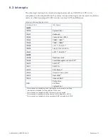
The following section provides an overview of the registers located in the I/O
address area of the CR9.
NOTE
The address location of PCI devices such as SCSI or Ethernet are not described in the following tables
because the System BIOS automatically configures (PnP, Plug and Play) each PCI device to avoid address
conflicts. Many device drivers show the actual address locations after installation and loading.


