42 CP9*, CR9*, CT9* Celeron M/Pentium M
Publication No. HRMCP9 Rev. B
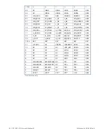
Table 5-6 Ethernet Connector Pin Assignments
Name 10/100BASE-TX
Name 1000BASE-T
Ethernet1, 2
TxD+
LP_DA+
1
TxD-
LP_DA-
2
RxD+
LP_DB+
3
NC
LP_DC+
4
NC
LP_DC-
5
RxD-
LP_DB-
6
NC
LP_DD+
7
NC
LP_DD-
8
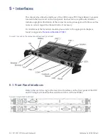
Two LEDs (LED1-green and LED2-yellow) are integrated in each of the RJ45
connector. These LEDs indicate the link status and activity of the interfaces.
Table 5-7 Ethernet LED Display Definitions
LED1 green
Function
On
Link
Off
No link
LED2 yellow
Function
On, blink
TX/RX activity
Off
No activity
The pin assignment at the rear I/O is compliant with the PICMG 2.16 (Switched
Packet Backplane) specification. The Ethernet interface can also be accessed via the
CTM12 transition module (see
Ethernet Interface 10/100/1000BASE-T P5000 and
) for connector type and pin assignment.
5.2.7
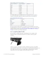
Serial Port COM1 P2201
The CR9 offers two RS232 serial ports. All COM ports are accessible via the
transition module, and additionally COM1 is accessible via the front panel
connector.
Figure 5-9 COM1 Location
COM1, 2 are software selectable for RS232 or RS422/485 operation within BIOS
setup. The RS485 output drivers can be enabled or disabled with the DTR signal. An
active DTR means the drivers to be enabled. When using the RS422 setting the
output drivers are always enabled and the DTR signal is not used.

