44 CP9*, CR9*, CT9* Celeron M/Pentium M
Publication No. HRMCP9 Rev. B
5.2.9
USB Interfaces P1680
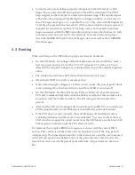
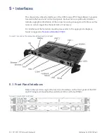
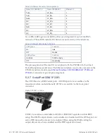
One USB channel is available at the front panel and four USB devices are available
on rear IO.
Figure 5-11 USB Connector Location
Figure 5-12 USB Connector Layout
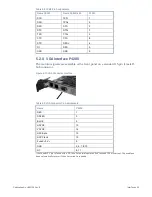
Table 5-10 USB Connector Pin Assignments
Name
P1680
Fused +5 V
a
1
USB0-
2
USB0+
3
GND
4
a
the Fused +5 V pin is fused with a 2 A fuse. For normal operation don’t exceed 100 mA current. The used fuse
does automatically recover if the over current is resolved.
5.2.10
PMC1 Connectors P6201, P6202, and P6203
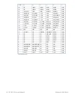
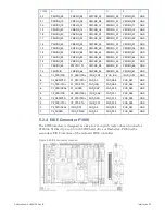
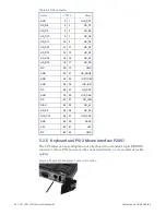
The following table lists the pin assignments of the onboard PMC1 connector. The
PMC1 slot is 64 bit and 66 MHz capable and works with the internal second PCI bus
of the P64H2 PCI Bridge. If an installed PMC card operates at 33 MHz only the PCI
bus speed is reduced to 33 MHz. With board revision V2 and higher, this slot is
PCI-X capable with 66/100/133 MHz. The PMC is electrical and mechanical
compliant to the specification IEEE 1386 and 1386.1 (check for possible height
incompatibility in
enhancements of the Processor PMC Standard VITA 32-2003. The enhancements
provide pins for a second device (IDSELB and REQB/GNTB) but do not support a
monarch PMC card.
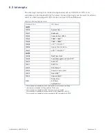
The PCI signaling voltage is fixed to 3.3 V. Nevertheless, PMC cards with 3.3 V or
5 V supply voltage can be used on this PMC slot.


