Publication No. HRMCP9 Rev. B
Installation 27
3.2.3
Video Monitor
Any VGA-compatible video monitor can be used initially for display output. The
CR9 offers front access to the video. Video can also be accessed via the J5 CPCI
connector on the rear I/O side. In order to get access to these pins it is necessary to
use a transition module.
3.2.4
Advice on Batteries
There is a danger of explosion if battery is incorrectly replaced. Replace only with
the same or equivalent type recommended by Abaco.
Dispose of used batteries according to instructions of Abaco and applicable local
regulations.
3.3 Installation of a Plug-in Board
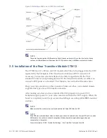
Boards are installed in a CPCI or VMEbus chassis by carefully sliding them into the
guide rails, inserting them all the way until the handles can be operated to seat and
lock the board in place. Handles typically have a lock (snap lever) to unlock them
when extracting a board. Older boards may have screws instead of handles to secure
the board in place.
Figure 3-1 6U Board Insertion into System Box
3.4 Installation of a Plug-on Module (Mezzanine)
After making sure that you have installed the mezzanine properly onto your carrier
board and installed both properly into a system shelf (subrack, card cage, enclosure),
apply power to your system. When the board is completely reset, the processor
should begin executing initial BIOS-resident routines indicated by the onboard
status LED blinking red.


