


Publication No. 500-657806-000 Rev. G
Standard Features 35
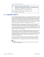
2.6 Integrated Peripherals
The CPCI-7806/CPCI-7806RC incorporate an SMSC Super I/O (SIO) chip. The SIO
provides the CPCI-7806/CPCI-7806RC with a standard floppy drive controller,
two 16550 UART-compatible serial ports, keyboard and mouse ports, and general
purpose I/O for system functions. The floppy, keyboard and mouse ports are
available via the CompactPCI backplane connectors and can be accessed with the
appropriate rear transition board. The serial port is accessed via the front panel.
Both serial ports are also routed to the CompactPCI J3 connector.
The parallel IDE interface is provided by the Intel I/O Controller Hub chip. The
IDE interface supports two channels known as the primary and secondary
channels. The secondary channel is routed onboard to the optional CompactFlash
socket. The primary channel is routed out of the CompactPCI backplane to a rear
transition board which terminates into a standard 40-pin header. This channel can
support two drives, a master and slave.
The IDE interface on the CPCI-7806/CPCI-7806RC supports Ultra ATA/33, Ultra
ATA/66 and Ultra ATA/100 drives and automatically determines the proper
operating mode based on the type of drive used. In order to properly function in
the Ultra ATA/100 mode, a special 80 conductor cable must be used instead of the
standard 40 conductor cable. This cable is typically available from the Ultra
ATA/100 drive manufacturer.
A Dual Serial ATA Drive Interface is also provided by the I/O Controller Hub.
These serial ATA ports can be used alone or in limited conjunction with the
parallel IDE interface. A single serial ATA drive can be connected to each port.
NOTE
Selection of drive type (parallel or serial), along with detailed IDE/ATA selections is available in the
CMOS Advanced BIOS Setup Menu.
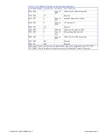
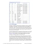
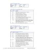
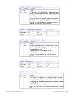
Table 2-5 NMI Register Bit Descriptions
Status Control Register (I/O Address $061, Read/Write, Read Only)
Bit 7
SERR# NMI Source Status (Read Only) - This bit is set to 1 if a system board agent detects
a system board error. It then asserts the PCI SERR# line. To reset the interrupt, set Bit 2 to
0 and then set it to 1. When writing to port $061, Bit 7 must be 0.
Bit 2
PCI SERR# Enable (Read/Write) - 1 = Clear and Disable, 0 = Enable
Enable and Real-Time Clock Address Register (I/O Address $070, Write Only)
Bit 7
NMI Enable - 1 = Disable, 0 = Enable