


104
Leak Testing
All components of gas supply system,
including manual shut off valves and the
piping in the interior of the unit, shall be leak
tested with a soap solution before operating
the appliance and at least on an annual basis
thereafter.
All gas fired heat exchangers are completely
tested at the factory before shipment. This
will remove nearly all of the oils that have
been used in the manufacturing process.
However, trace amounts may remain. When
performing the initial startup at the jobsite, it
is highly recommended that people or any
other living animals, which may be sensitive
to the residual odors or gases, NOT be
present in the conditioned space during the
startup. In all cases, including the initial
factory firing and testing, any of the gases
will be under the acceptable level of
concentration for human occupancy.
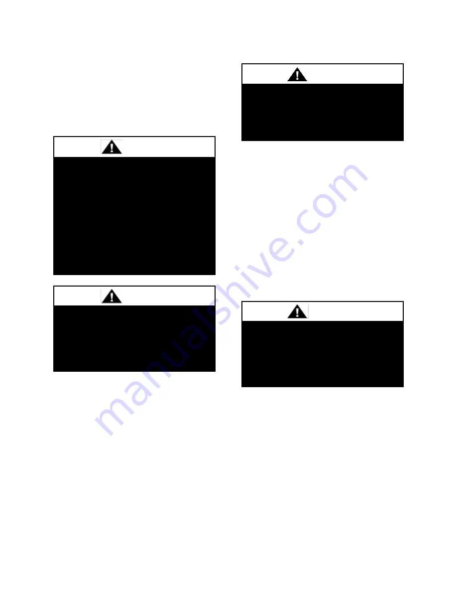
Do not use open flame or other source
of ignition for leak testing. Fire or
explosion
could
result
causing
property damage, personal injury, or
death.
DANGER
Those sensitive to odors or gases
from trace amounts of residual oils
must NOT be present
in the
conditioned space during the startup
of a gas fired installation.
WARNING
LEAK CHECK GAS PIPE
The gas pipe in the unit shall be
checked for leaks before startup. Leak
checking is the responsibility of the
installing contractor. All connections
shall be checked for leaks annually
after installation. Failure to leak check
could result in fire, explosion, or other
hazardous situations.
DANGER
Some soaps used for leak detection
can be corrosive to certain metals.
Rinse piping thoroughly after leak test
has been completed.
CAUTION
Summary of Contents for RN Series
Page 2: ......
Page 32: ...32 Figure 5 RN Series 6 8 and 10 ton Unit Isolator Locations ...
Page 33: ...33 Figure 6 RN Series 9 and 11 15 ton Unit Isolator Locations ...
Page 34: ...34 Figure 7 RN Series 16 25 and 30 ton Unit Isolator Locations ...
Page 35: ...35 Figure 8 RN Series 26 31 50 60 and 70 ton Unit Isolator Locations ...
Page 36: ...36 Figure 9 Steel Mounting ...
Page 102: ...102 Figure 56 Example 6 50 60 70 ton through the Base Gas Piping ...
Page 105: ...105 Gas Heater Operating Instructions Figure 58 Gas Heater Instructions ...
Page 129: ...Maintenance Log E Coated Coil ...