7
INSTALLATION cont.
OROA Valve:
This system uses a nonadjustable head pressure
control valve that performs the function of
limiting the flow of liquid refrigerant from the
condenser and at the same time regulates the
flow of the hot gas around the condenser to the
receiver. The valve setpoint is 180 psig. This
valve is called an OROA valve (Open on Rise of
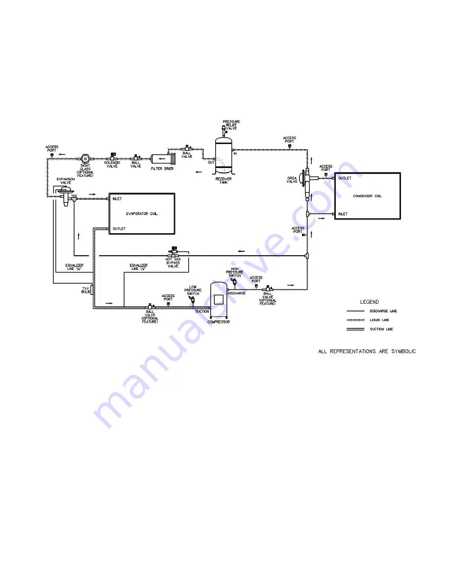
Outlet pressure). The following schematic
shows an example system using the OROA
valve.
Piping Schematic of Example system using the OROA valve.
ORI/ORD Valves:
This system uses a two-valve arrangement. The
head pressure control valve is an inlet pressure
regulating valve and responds to changes in
condensing pressure. This valve is located in the
discharge of the condenser and is called an ORI
valve (Open on Rise of Inlet pressure). As the
ambient temperature drops, the condenser
capacity increases and the condensing pressure
falls, causing the ORI to modulate toward the
closed position. The condenser bypass valve is a
pressure differential valve that responds to
changes in the pressure differential across the
valve. This valve is called an ORD valve (Open
on Rise of Differential pressure). As the ORI
starts to restrict liquid flow from the condenser, a
pressure differential is created across the ORD.
When the differential reaches the setpoint, the
ORD starts to open and bypass hot gas to the
liquid line. The ORI valve is adjustable from 65
to 225 psig (factory setting of 180 psig). The
ORD is not adjustable. On refrigeration systems
that are too large for a single ORI and ORD
valve, there will be two ORI and two ORD
valves in parallel. The schematic on the
following page shows an example system using
the ORI/ORD valves.


