


is
Instruction manual SGS
79
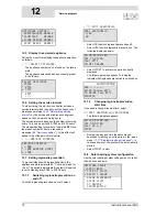
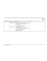
13.3 Troubleshooting table for displayed errors
Displayed errors
Code + Description
Cause
Solution
Remark
S01 (blocking error)
Open circuit from
temperature sensor T2
at bottom of the tank
Sensor is not (correctly)
connected
Connect the sensor lead to JP3
See the SGS electrical diagram
(17 "Appendices")
Damaged cable or
defective sensor
Replace the sensor
To replace the necessary parts, you must contact your installation
engineer
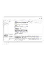
S02 (blocking error)
Open circuit in sensor 1
of temperature sensor
T
1
at the top of the
tank
(1)
.
Sensor is not (correctly)
connected
Connect the sensor lead to JP5
See the SGS electrical diagram
(17 "Appendices")
Damaged cable or
defective sensor
Replace sensor T
1
To replace the necessary parts, you must contact your installation
engineer
S03 (blocking error)
Open circuit in sensor 2
of temperature sensor
T1 at the top of the tank
(1).
Sensor is not (correctly)
connected
Connect the sensor lead to JP5
See the SGS electrical diagram
(17 "Appendices")
Damaged cable or
defective sensor
Replace sensor T
1
To replace the necessary parts, you must contact your installation
engineer
S04 (blocking error)
Open circuit from
dummy 1
Dummy is not
(correctly) connected
Connect the dummy sensor (dummy sensor 1 and 2) leads to JP4. See the SGS electrical diagram
(17 "Appendices")
Defective dummy
Replace the dummy sensor
To replace the necessary parts, you must contact your installation
engineer
S05 (blocking error)
Open circuit from
dummy 2
Dummy is not
(correctly) connected
Connect the dummy sensor (dummy sensor 1 and 2) leads to JP4. See the SGS electrical diagram
(17 "Appendices")
Defective dummy
Replace the dummy sensor
To replace the necessary parts, you must contact your installation
engineer
S06 (blocking error)
Open circuit from
temperature sensor S4
at bottom of storage
tank
Sensor is not (correctly)
connected
Connect the sensor lead to J14 (port 1 and 3) of the solar controller See the SGS electrical diagram
(17 "Appendices")
Damaged cable or
defective sensor
Replace the sensor
To replace the necessary parts, you must contact your installation
engineer
Summary of Contents for SGS - 100
Page 1: ...80 100 Installation User and Service Manual Installation User and Service Manual...
Page 2: ...www aosmithinternational com your installer...
Page 4: ...4 Instruction manual SGS gis...
Page 8: ...Table of contents 8 Instruction manual SGS...
Page 12: ...Introduction 12 Instruction manual SGS 1 gis...
Page 44: ...Installation 44 Instruction manual SGS 3 is...
Page 62: ...Shutting down 62 Instruction manual SGS 10 gis...
Page 92: ...Maintenance frequency 92 Instruction manual SGS 14 is...
Page 101: ...Instruction manual SGS 101 is...
Page 106: ...Appendices 106 Instruction manual SGS 17 is...


