


Instruction manual SGS
39
is
3.12.2
Connecting the mains power
Note
Just as with the appliance controller, the solar heating system controller
must have a permanent electrical connection to the mains power supply. There
must be a double-pole isolator installed in the permanent connection. This is the
same double-pole isolator as installed between the mains power supply and the
appliance itself. Whenever this isolator is operated, both controllers can be
switched on or off.
1. Connect earth, live and neutral to terminals 1 through 3
2. Fit the cables in the strain relief.
3. Connect the power cable to the isolator.
4. Continue
(3.12.3 "Connecting pump station - modulating pump")
.
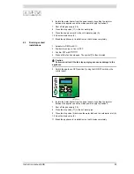
3.12.3
Connecting pump station - modulating pump
The pump station contains a modulating pump (4-wire connection). You must
connect this pump to the controller of the solar heating system.
1. Connect earth, live and neutral to terminals 10 through 12.
2. Connect the fourth lead to terminal 13
3. Fit the cables in the strain relief.
4. Continue
(3.12.4 "Connecting solar collector")
.
3.12.4
Connecting solar collector
Note
This sensor must be mounted in the solar collector; refer to the solar
collector installation manual.
Connect the sensor to the appliance as follows:
1. Connect the sensor to terminal 2 and 4 of J13.
2. Fit the cables in the strain relief.
3. Continue
(3.12.5 "Connecting tank sensor")
.
3.12.5
Connecting tank sensor
Note
This sensor is already mounted in the tank prior to delivery. The sensor is
mounted between the inlet and outlet of the heat exchanger. However, you must
still connect the lead to the solar heating system controller.
1. Connect the sensor lead with the blade connectors to the sensor.
2. Connect the other end to terminals 2 and 4 of J14.
3. Fit the cables in the strain relief.
4. Continue
(3.12.7 "Connecting communication cable")
.
3.12.6
Connecting top tank sensor
1. Connect the sensor lead with the blade connectors to the sensor.
2. Connect the other end to terminals 1 and 3 of J14.
3. Fit the cables in the strain relief.
4. Continue
(3.12.7 "Connecting communication cable")
.
Summary of Contents for SGS - 100
Page 1: ...80 100 Installation User and Service Manual Installation User and Service Manual...
Page 2: ...www aosmithinternational com your installer...
Page 4: ...4 Instruction manual SGS gis...
Page 8: ...Table of contents 8 Instruction manual SGS...
Page 12: ...Introduction 12 Instruction manual SGS 1 gis...
Page 44: ...Installation 44 Instruction manual SGS 3 is...
Page 62: ...Shutting down 62 Instruction manual SGS 10 gis...
Page 92: ...Maintenance frequency 92 Instruction manual SGS 14 is...
Page 101: ...Instruction manual SGS 101 is...
Page 106: ...Appendices 106 Instruction manual SGS 17 is...


