Filling
48
Instruction manual SGS
5
gis
Note
In the above diagram, there is a non-return valve in the station. This may
only be used in closed (pressure) systems. In systems with drain back, it is
prohibited to fit a non-return valve in the solar heating system.
5.2
Filling unvented
installations
To fill the appliance, proceed as follows:
1. Open the stop valve (11) in the hot water pipe and, if present, the stop valves
(4) for the circulation pump (6).
2. Close the drain valve (9).
3. Open the nearest hot water draw-off point (14).
4. Open the stop valves (11) between the storage tank and the appliance.
5. Open the stop valve (4) on the cold water side (A) so that cold water flows
into the appliance.
6. Completely fill the appliance. When a full water jet flows from the nearest
draw-off point, the appliance is full.
7. Bleed the entire installation of air, for example by opening all draw-off points.
8. The appliance is now under water supply pressure. There should be no
water coming out of the expansion valve (15) or out of the P-valve (23). If
there is, the cause might be:
-
The water supply pressure is greater than the specified 8 bar.
Rectify this by fitting a pressure reducing valve (1).
-
The expansion valve in the protected cold supply setup is defective or
incorrectly fitted.
5.3
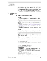
Filling vented
installations
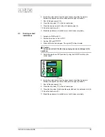
To fill the appliance, proceed as follows:
1. Open the stop valve (11) in the hot water pipe and, if present, the stop valves
(4) for the circulation pump (6).
2. Close the drain valve (9).
3. Open the nearest hot water draw-off point (14).
4. Open the stop valves (11) between the storage tank and the appliance.
5. Open the stop valve (4) on the cold water side (A) so that cold water flows
into the appliance.
Legend
Only applicable numbers are mentioned.
1. pressure-reducing valve (mandatory if the mains
water pressure exceeds 8 bar)
3. T&P valve (mandatory)
4. stop valve (recommended in pipe C and mandatory in
pipe A)
5. non-return valve (mandatory)
6. circulation pump (optional)
9. drain valve
10. manual gas valve (mandatory)
11. service stop valve (recommended)
12. temperature gauge (recommended)
13. condensation drainage (mandatory)
14. hot water draw-off points
16. expansion vessel (mandatory)
17. 3-way aeration valve (recommended)
18. water tank
19. float valve
23. pressure valve (mandatory)
26. air bleed (mandatory)
37. combined Q/T sensor (optional)
38. solar heating system pump station (modulating -
mandatory)
A. cold water supply
B. hot water supply
C. circulation pipe
D. gas supply
E. overflow pipe
F. heat exchanger supply
G. heat exchanger return
H. overflow safety
S1.collector sensor (mandatory)
S2.tank sensor (mandatory)
S3.top tank sensor (mandatory)
S4.heat exchanger discharge sensor (optional)
Summary of Contents for SGS - 100
Page 1: ...80 100 Installation User and Service Manual Installation User and Service Manual...
Page 2: ...www aosmithinternational com your installer...
Page 4: ...4 Instruction manual SGS gis...
Page 8: ...Table of contents 8 Instruction manual SGS...
Page 12: ...Introduction 12 Instruction manual SGS 1 gis...
Page 44: ...Installation 44 Instruction manual SGS 3 is...
Page 62: ...Shutting down 62 Instruction manual SGS 10 gis...
Page 92: ...Maintenance frequency 92 Instruction manual SGS 14 is...
Page 101: ...Instruction manual SGS 101 is...
Page 106: ...Appendices 106 Instruction manual SGS 17 is...


