background image

4

3T-MOTORS Radio tubular motors

  |  Safety instructions

GENERAL SAFETY INSTRUCTIONS

IMPROPER USE

PROPER USE

 WARNING: Important safety instructions.  

  Follow all instructions as incorrect installation may result in serious injury.

 WARNING: The drive must be disconnected from the power source during cleaning, maintenance and replacement of parts.

 Danger to life from electric shock when working on electrical equipment. 

 The electrical connection, installation and commissioning of the receiver may only be carried out by qualified personnel.  

 Before installing the drive, remove all unnecessary cables and disable all devices,  

  that are not required for operation with power.

 The relevant regulations and guidelines must be followed without fail, to avoid damage to persons and objects.

 Observe safety instructions according to EN 60 335-2-97: The power supply cable of the drives must be laid internally.

 Installation according to DIN 18073: The roller shutter box cover must be easily accessible and removable.

 Installation according to EN 60335: Only switches / pushbuttons / switching devices with a minimum contact opening 

  of 3 mm may be used, furthermore the up and down direction must be interlocked against each other.

 When installing in damp rooms, observe regulations (VDE 0100, part 701 and 702).

 These drives can be connected in parallel without an isolating relay or central control.  

  In this case, the max. output power of the command transmitter (timer or otherwise) must be observed.

 Do not use defective devices: Never use defective equipment. 

  Periodically inspect the equipment for imbalance and signs of wear or damage to cables and suspension springs. 
  Do not use equipment if repair or touch-up is necessary. 
  There is a risk of personal injury and property damage due to electric shock or short circuit.

 Retain the instructions for future reference.

 Use tubular motors only for automating shutters.

 Only use original components and original accessories from the manufacturer. 

 The mains connection cable of the drives must be laid internally in the empty conduit up to the junction box. 

  The local electrical regulations must be observed.

 For the electrical connection of the tubular motors, a 230 V / 50 Hz 

  power connection with fuse must be available at the installation site.

 Inspect the installation frequently for imbalance and signs of wear or damage to cables and springs. 

  Do not use if repairs or adjustments are required.

Please read these important safety instructions before commissioning!

Incorrect installation can cause serious personal injury and damage to property. 
The warranty claim expires in case of non-observance of this user information with all contained notes and regulations.
In case of non-observance of these instructions, the manufacturer or supplier shall not be liable for any personal injury or property damage incurred.

 SAFETY INSTRUCTIONS

This symbol indicates danger due to electrical energy. 

Danger to persons and objects may arise if the 

associated information is not observed!  

This symbol indicates information about general danger. 

Non-observance can mean danger to 

persons and objects!

This symbol indicates important information that can 

ensure safe and proper use of the device.

 Persons are to be instructed with the correct operation of the tubular motor. 

 The roller shutter movement must be monitored in order not to endanger persons. 

 Do not allow children to play with motor controls.

 Store the handheld transmitter in such a way that unintentional operation is prevented (e.g. by children playing).

 The device can be used by children aged 8 years and above and persons with reduced physical, sensory or mental 

  capabilities or lack of experience and knowledge, if they have been given supervision and instruction concerning use 
  of the appliance in a safe way and are aware of the hazards involved.

 Children are not allowed to play with the equipment.

 If the power supply cord of this device is damaged, it must be replaced by the manufacturer or its customer service 

  or a similarly qualified person to prevent hazards.

Summary of Contents for 3T-MOTORS 3T35-10RB

Page 1: ...trol via smart phone tablet PC or via voice commands with Alexa or Google Assistant INTELLIGENT DRIVES CONTROLS FOR SHUTTERS AND AWNINGS INSTALLATION OPERATING INSTRUCTIONS Instructions and notes for installation and operation 3T MOTORS Radio shutter awning motors with electronical limit switches Attention It is important for the safety of persons to follow these instructions Keep these instructio...

Page 2: ...g motor wiring Page 13 Notes on the setting of the motor Programming notes Page 14 Functions P1 button Page 14 Programming Pairing handheld transmitter Page 15 Changing the direction of rotation of the radio motor Page 15 Programming end positions Page 16 17 Programming Intermediate position Page 17 Programming handheld transmitter settings Page 18 20 Rocker switch Page 21 Troubleshooting Page 21 ...

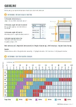
Page 3: ...ce Friction losses must be taken into account rail guidance of approx 10 Roller shutter area m x Weight roller shutter material m Weight roller shutter kg 10 Friction losses Required traction force kg Example PVC Roller shutter area 3 00 m x Weight roller shutter material 5 kg 15 kg Weight roller shutter 10 Friction losses 16 5 kg Required traction force Material PVC Aluminum Light Aluminum Heavy ...

Page 4: ...nd original accessories from the manufacturer The mains connection cable of the drives must be laid internally in the empty conduit up to the junction box The local electrical regulations must be observed For the electrical connection of the tubular motors a 230 V 50 Hz power connection with fuse must be available at the installation site Inspect the installation frequently for imbalance and signs...

Page 5: ...m 60 kg 9 m 7 m 200 W 4 W 15 U min 22 U 230 V 656 mm 635 mm 3 m 4 min IP44 4260601764107 3T45 40RB 40 Nm 80 kg 11 m 9 5 m 228 W 4 W 15 U min 22 U 230 V 656 mm 635 mm 3 m 4 min IP44 4260601764114 3T35 10RB 10 Nm 25 kg 5 25 m 4 2 m 144 W 4 W 17 U min 30 U 230 V 584 mm 568 mm 3 m 4 min IP44 4260601764060 3T35 13RB 13 Nm 40 kg 7 m 5 5 m 144 W 4 W 14 U min 30 U 230 V 584 mm 568 mm 3 m 4 min IP44 426060...

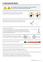
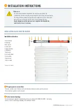
Page 6: ... Steel shafts with an internal fold will damage and destroy the motor Grinding marks of any kind on the motor housing will void the warranty The inspection cover of the roller shutter box must be easily accessible and removable We recommend using a tubular motor with a power 10 higher than the weight of the shutter to compensate for the frictional resistance of the rail guide See Guideline Determi...

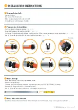
Page 7: ...iversal bearing and cover cap bearing 3T45 30RB 3T45 40RB clip bearing Use one of the two motor bearings depending on the installation situation 1 2 3 4 5 6 7 8 9 10 11 Please note The motor can be installed on the right hand side as well as on the left hand side If the direction of rotation is reversed please exchange the wires for the up and down direction The setting of the end positions is onl...

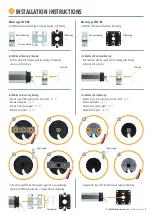
Page 8: ... clip bearing Installation with universal bearing Push the motor with the square into the opening of the bearing and secure with cotter pin Installation with cover cap bearing Remove screws from metal plate on motor head fig 2 1 Remove metal plate fig 2 2 Remove motor square spigot fig 2 3 Reattach metal plate fig 2 4 Slide motor type 3T45 R without square spigot into cover cap bearing and secure ...

Page 9: ... 4 7 4 8 5 Mount bearings Remove old wall bearing on motor side left or right installation possible Mount motor bearing at this point 2 mounting options Universal bearing cotter pin and cover cap bearing securing clips 3T45 30RB 3T45 40RB clip bearing Please mount the bearings so that the limit switches are freely accessible Make sure that the roller shutter motor with the shaft unit sits horizont...

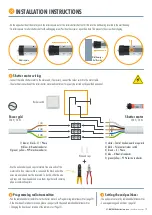
Page 10: ...trical connection of the roller shutter motor and control unit may only be carried out by qualified personnel 1 8 Programming radio transmitter Pair the radio handheld transmitter to the shutter motor See Programming radio transmitter page 15 If the direction of rotation is reversed please change it with the paired radio handheld transmitter Changing the direction of rotation of the radio motor Pa...

Page 11: ...40 only use shafts with an external fold Steel shafts with an internal fold will damage and destroy the motor Explanation Avoid overstressing and resulting premature aging of the motor by using the correct suspension springs and the correct roller shutter shaft with external fold Keep in mind that the motor housing has a diameter of 35 mm and the roller shutter shaft SW40 has an outer diameter of ...

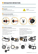
Page 12: ...he support tube fig 3 4 Remove the crank mechanism fig 3 5 Attention Awning arms are under strong tension 2 1 2 2 2 3 2 4 3 1 3 2 3 2 3 4 Remove the shaft capsule from the shaft fig 3 6 If the shaft capsule is tight use a hammer and screwdriver Be careful not to damage the shaft Push the awning motor with shaft adapter first into the shaft fig 3 7 Make sure motor head limit switch adapter are flus...

Page 13: ...de the wire end caps onto the wire ends and press them together with crimping pliers or combination pliers 5 Programming radio transmitter Pair the radio hand held transmitter to the awning motor See Programming radio transmitter page 15 If the direction of rotation is reversed please change it with the paired radio hand held transmitter Changing the direction of rotation of the radio motor Page 1...

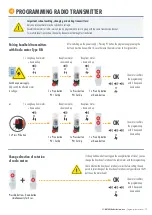
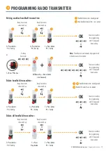
Page 14: ...transmitter that was paired first will be overwritten Important explanations on setting and programming the motor Please read carefully before setting the motor NOTES ON THE SETTTING OF THE MOTOR FUNCTIONS P1 BUTTON 1 Pairing handheld transmitter Pairing additional handheld transmitters The motor is ready for pairing a handheld transmitter further handheld transmitters 3 x beep from motor pairing ...

Page 15: ... Long beep from motor down and up Press Up button Down button simultaneously for 2 sec If the up and down buttons triggers the wrong direction of travel you can change the direction of rotation of the radio motor with this programming Check whether the direction of rotation is correct before setting the end points A later change of the direction of rotation is only possible via the P1 button on th...

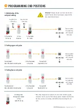
Page 16: ... upper end point 1 x Press Stop button to stop motor The motor confirms the programming with 3 beeps and down and up OK 3 Setting lower end point Press and hold Stop button for 5 sec Press Down button Move roller shutter to desired position 1 x Press Stop button to stop motor The motor confirms the programming with 3 beeps and down and up OK When setting the upper and lower end points the motor ca...

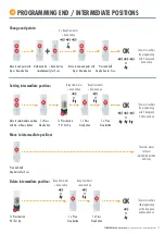
Page 17: ... programming with 3 beeps and 3 x down and up OK Move to intermediate position with Up or Down button 1 x Press Stop button 1 x Press button P2 Set Up 1 x Press Stop button Beep from motor down and up Beep from motor down and up Move to intermediate position The motor moves to the set intermediate position and stops Press and hold Stop button for 2 sec 1 x Press Stop button Beep from motor down an...

Page 18: ...ess P1 button 3 x Beep from motor Note The endpoints must already be programmed to be able to use this method 1 x Press button P2 Set Up Delete handheld transmitter Beep from motor down and up 1 x Press button P2 Set Up Beep from motor down and up The motor confirms the programming with 3 beeps and down and up OK a b Handheld transmitter already paired b Handheld transmitter to be deleted a b 1 x ...

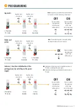
Page 19: ...otor confirms the programming with 3 x beep and down and up OK Activate deactivate initialization of the pairing process by switching on the power supply ON Initialization of the pairing process for handheld transmitters via P1 button or switching on the power supply OFF Initialization of pairing process for handheld transmitter only via P1 button 1 x Press Up button 1 x Press Up button Beep from ...

Page 20: ...iate position Delete intermediate position P2 a P2 a P2 b P1 Up b Down b P2 a P2 a P2 b P2 Stop P2 P2 Up Ab P2 Down P2 P2 Up Auf P2 Up P2 Up Stop Stop 5 sec Down Stop Stop 5 sec During ascent or descent P2 Up Up Down simultaneously 5 sec Up or Down Stop 5 sec Down Up Down simultaneously 5 sec Up or Down Stop 5 sec Up or Down Stop P2 Stop Stop Stop 2 sec P2 Stop Stop a transmitter already paired b ...

Page 21: ...dy for operation again the motor cannot be paired Radio motor was not set to ready to learn by switching power supply off on or the P1 key Switch off switch on power supply or press P1 button and perform teach in procedure again Pairing by pressing the keys must be done within 10 sec after switching on the power supply and beeping of the motor Group channel 0 set for multi channel transmitters can...

Page 22: ...Richtlinien erfüllt 2014 30 EU EMV Richtlinie 2014 53 EU RED Richtlinie 2011 65 EU RoHS Richtlinie 2012 19 EU WEEE Richtlinie 2014 35 EU Niederspannungsrichtlinie angewandte Standards und Verordnungen EN 60335 1 2012 A13 2017 EN 60335 2 97 2006 A12 2015 EN 60950 1 2006 A2 2013 EN 300 220 2 V3 1 1 EN 301 489 1 V1 9 2 EN 301 489 3 V1 6 1 EN 55014 1 2017 EN 55014 2 2015 EN 61000 3 2 2014 EN 61000 3 3...

Page 23: ...140 cm 160 cm Suspension spring Maxi Required when using roller shutter motors Maxi spring up to 65 mm profile height For roller shutter shaft SW60 Powder coated Anti burglary effect Pick up width 100 mm Total length 215 mm Suspension spring Mini Required when using roller shutter motors For roller shutter shaft SW40 Powder coated Anti burglary effect Pick up width 100 mm Total length 140 mm Ball ...

Page 24: ... FOR SHUTTERS AND AWNINGS Service and Quality make the difference Social Media Links Info news and tips on roller shutters awnings smart home and more 3T Components GmbH Co KG Bahnhofstr 34 55578 Wallertheim Email info 3t components de Tel 49 0 6732 600 03 69 Fax 49 0 6732 600 54 30 www 3t components de Opening hours Monday Friday 8 00 17 00 ...

Reviews: