3e–525C–3 Wireless Access Point
Chapter 2: Hardware Installation
16
29000171-001 A
3e–525C–3 Wireless Access Point
Chapter 2: Hardware Installation
29000171-001 A
17
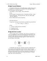
The equation of the width of Fresnel Zone is:
Where
W = Width of the Fresnel Zone (in feet)
D = Distance between the antennas (in miles)
F = Frequency in GHz
When the transmit distance of RF signal is longer than seven miles,
the curvature of the earth may be a factor and require the antenna put at
higher location. The additional antenna height can be calculated by below
formula:
Where
H = Height of earth bulge (in feet)
D = Distance between antennas (in miles)
Outdoor Protection Kit Installation
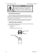
If any portion of this system (3e–525C–3 enclosure, antennas, cables
etc.) is mounted outdoors, it is strongly recommended that the Outdoor
Protection Kit (3e-OPK-3) for this product be used. This kit contains
lightning arrestors and ground cables designed for this product.
If the system is mounted outdoors where CE Mark certification is
required, use of the Outdoor Protection Kit (or equivalent) is
MANDATORY
. Failure to install this protection will void the warranty.
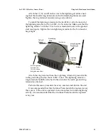
The Outdoor Protection Kit (3e-OPK-3 contains the following items:
• 10-inch, 10AWG wire with #8 ring terminal on one end and a #10
ring terminal on the other end
• 12-inch, 10 AWG wire with #8 ring terminal on one end and a #10
ring terminal on the other end
• 18-inch, 10 AWG wire with #8 ring terminal on one end and a #10
ring terminal on the other end
• Three lightning arrestors, Reverse N Polarity
NOTE
: You (the user) are required to ensure that the connection to a
proper earth ground is made by properly certified and authorized person-
nel and must conform to all applicable codes and regulations. The materi-
als required to connect to a proper ground are defined by local conditions
and must be procured locally to ensure the correct safety environment is
achieved. The cable used to connect to a proper ground must be AWG 10
or heavier. This cable should be kept as short as possible.

