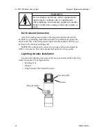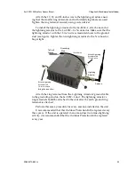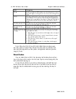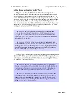
3e–525C–3 Wireless Access Point
Chapter 2: Hardware Installation
14
29000171-001 A
3e–525C–3 Wireless Access Point
Chapter 2: Hardware Installation
29000171-001 A
15
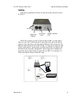
Cabling
The following illustration shows the external cable connectors on the
3e–525C–3.
Bridge Antenna
Port
Ground
LAN Port
"Local"
WAN Port
"Uplink"
The WAN connector is used to connect the 3e–525C–3 to the organi-
zation's LAN. The WAN connector is routed from the unit to the power
injector which runs DC power through the Ethernet cable to the unit. The
Ethernet cable is thus run from the 3e–525C–3 to the power injector which
is then connected to a power source and the wired LAN. A second (LAN
Port) Ethernet connector is designed for use during initial configuration
only. This uses an RJ45 cable to connect the 3e–525C–3 to a laptop. The
following diagram demonstrates the setup.
Connect
RF Antenna
for AP
Connect
RF Antenna
WAN
Ethernet
Port
110V
Power
Ethernet switch/hub
Connect
RFAntenna
for Bridge/
Repeater
LAN
Ethernet
Port
Power Injector

