40 | 3DGence ONE
The area in which the models to be printed can be arranged. It is recommended to print at the distance of at least 5 mm
from the workspace edge.
The side indicated by the arrow is the place where the physical front of the printer and operator panel is placed.
This displays the virtual printer axes.
Pressing this button will initialize the process of calculating machine paths (g-code) for selected print settings. The pro-
cess progress bar will appear on the status bar. The solid appearance in the main software window will change to show
the graphic representation of movements. After the work is completed, the software will enter the path preview mode to
display the paths to be carried out by the printer, as de-scribed in the subsequent chapter.
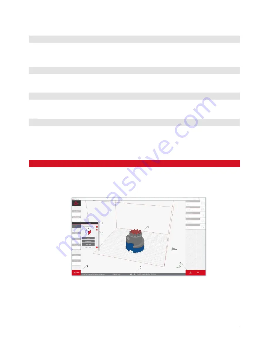
The solid appearance in the main software window shows the graphic representation of the printhead movements. This
view enables to preview the generated layers, verify print settings and save the .gcode executable file.
The model and print profile modification options are blocked. To change them, return to the main interface.
1. View options.
2. Previewing active model layer.
3. Return to the main interface function.
4. Representation of anticipated material paths from .gcode file.
5. Status bar.
6. .gcode file saving button.
4.7 Virtual buildplate of the machine
4.8 Arrow indicating the physical front of the machine
4.9 Printer axis preview
4.10 Prepare to print button
5. PREVIEW MODE OF .gcode
Summary of Contents for ONE
Page 1: ...USER MANUAL 3DGence ONE ...
Page 2: ......


