background image


Page 

6

 of 

44


3DGence Material Management System | version 1 | 03.2022 

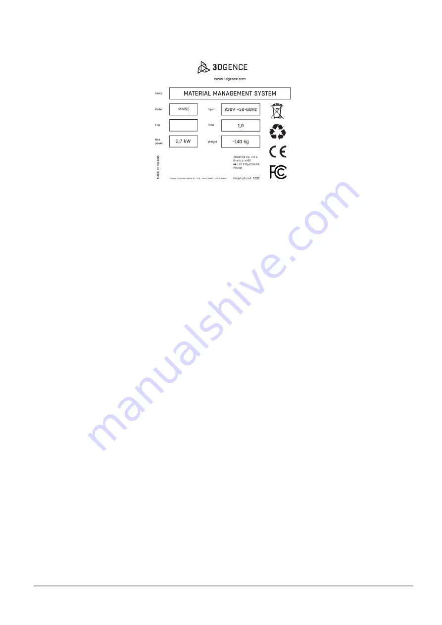
3DGence technical support department will automatically receive the serial number of your device in your request. The serial 
number starts with a symbol: S/N MMS1 which should be specified when contacting 3DGence technical support. 


Fig. 

1

 Nameplate of the device


4.


THE IMPORTANCE OF THE MATERIAL DRYING PROCESS FOR THE PRINTING PROCESS 

Undesirable degradation processes occurring in plastics processing are well known and preventive steps are clearly defined in 
the technical data sheets of the base resins. One type of thermoplastic degradation is degradation by hydrolysis - the separation 
of a polymer chain caused by water molecules adhering to the chain. During printing, by heating the filament in the head to a 
high temperature, water is removed from its volume. Excess water during the printing process can cause a number of visual 
defects (air bubbles, cracking of elements, colour change) and a decrease in the strength properties of the print.  

For 3D printing, the most important preparatory step for the printing process is to provide a build material with an optimal, 
low water content. In conventional plastics processing (e.g. injection), the permissible water content in the material does not 
exceed 0.5% of the weight of the material, and in most cases this value is below 0.08%. 

A number of material conditioning methods are used to ensure a material with the correct water content. One of these is dry 
air drying which is able to dry the material down to as little as 0.01%. The 3DGence Material Management System uses a similar 
dry process air delivery technology. The air passing through the desiccant cartridge provides optimum conditions for effective 
material preparation, eliminating the potential risk of the print defects described above. 

Summary of Contents for MMS1

Page 1: ...INSTRUCTION MANUAL Original instruction 3DGence Material Management System...

Page 2: ...this document relate solely to the specific 3DGence device Neither 3DGence nor its related parties in particular those involved in the development manufacturing or supply of this product shall be lia...

Page 3: ...Power requirement 12 2 CONTENTS OF THE SET 12 3 UNPACKING THE MMS 13 4 STEPS BEFORE STARTING THE DEVICE 13 5 START UP 3DGENCE MATERIAL MANAGEMENT SYSTEM 13 5 1 Connecting to power source and switching...

Page 4: ...29 1 2 4 Storage settings 29 2 Work with the 3DGence Material Management System device 30 2 1 Material statuses in the 3DGence Material Management System device 31 V OPERATION OF THE DEVICE 32 1 FIRMW...

Page 5: ...Their meaning is described in this manual 2 TECHNICAL SPECIFICATIONS OF THE DEVICE The 3DGence Material Management System is an industrial device designed to Store reels of printing materials Carry ou...

Page 6: ...option Process settings for material preparation Preset Edit in CUSTOM option Recrystallisation process settings Pre defined SOFTWARE Device monitoring and archive Locally and in the 3DGence CLOUD Sof...

Page 7: ...s removed from its volume Excess water during the printing process can cause a number of visual defects air bubbles cracking of elements colour change and a decrease in the strength properties of the...

Page 8: ...TECTION You will need to wear the protective gloves to perform the operations described 1 2 General safety practices Do not install the device in open space outdoors in damp areas or areas exposed to...

Page 9: ...crushing hands The symbol indicates that there is a hazard that could cause your hands to be crushed Warning of existing moving machine parts This symbol indicates that there is a hazard which may cau...

Page 10: ...es of the printer must be accessible for among other things loading of the materials or maintenance work in accordance with the manufacturer s recommendations the operator may occupy a position at the...

Page 11: ...ge 10 of 44 3DGence Material Management System version 1 03 2022 Fig 3 Maximum size of the 6 chamber MMS width Fig 4 Maximum size of the 3 chamber and 6 chamber MMS depth and width 1090mm 1560mm 1740m...

Page 12: ...44 3DGence Material Management System version 1 03 2022 Fig 5 Minimum distances of the MMS from walls and other objects Fig 6 Minimum distance to be kept from the top of the device 500mm 670mm 100mm 1...

Page 13: ...20A plug The 4 and 6 chamber versions base device expansion module require two power supply lines each in NEMA L6 20A standard 1 8 Power requirement The power requirement mainly depends on the type of...

Page 14: ...power supply and or undertake repairs on your own check that there are no objects or loose parts in the device chambers that could cause jamming or damage to the heating elements 5 START UP 3DGENCE M...

Page 15: ...er is connected and a connection via Wi Fi is selected in the network type record the Wi Fi record below becomes active and takes you to the list of available networks Once a network is selected the M...

Page 16: ...ence Material Management System easier and to make the rest of the manual easy to understand below you will find a series of drawings with descriptions of the most important components comprising the...

Page 17: ...wer 5 Desiccant cartridge 6 Seal of the chamber door Fig 11 3DGence Material Management System rear view 1 Mounting points for the 3 chamber extension 2 Air outlet from the chamber 3 Multi connector s...

Page 18: ...ively dry more materials for a device in the CUSTOM mode In the front part of the drawer there is an elongated notch into which the desiccant cartridge should be inserted The notch position guarantees...

Page 19: ...rt circuits and low voltage AC and DC overloads When high current surges occur the AC fuse activates protecting the electrical and electronic components of the MMS Before restarting ensure that all ma...

Page 20: ...f the 3 chamber extension set Expansion module Assembly parts of the extension module to the base unit Set of drawers and desiccant cartridges 32A 3 phase to 3x 1 phase power supply adapter 7 2 3 Prep...

Page 21: ...bracket of the extension module Then use the screws provided to connect the two devices together at five points The doors of the expansion module chambers can be opened to facilitate installation Fig...

Page 22: ...ts connecting the two devices Fig 16 Rear of the device how to install the bottom beam 6 Screw the top beam highlighted in blue in the figure below at 4 points at the same time laying the communicatio...

Page 23: ...the upper casing of the device Fig 20 Screwing place for the front cover 8 Connect the devices to the power supply according to the preferred method 9 Set the main switches of both devices to the ON p...

Page 24: ...2 Archive switch 3 Network settings button 4 Network device button 5 Current chamber temperature 6 Current chamber status 7 Chamber operating mode selection button 8 Notification centre button 9 Indi...

Page 25: ...ence If an event changes its status to inactive it will be moved to the printer log tab Clear alarm allows the event to be acknowledged and if possible the error to be cancelled and the acoustic alarm...

Page 26: ...o the screen related to network connection details 3DGence CLOUD transfers you to the screen related to the connection with 3DGence CLOUD Connection status informs about the status of the connection F...

Page 27: ...ng whether the device has been connected to the 3DGence CLOUD platform Printer serial number MMS serial number to be entered when adding the device to the 3DGence CLOUD web platform CLOUD PIN the code...

Page 28: ...settings Screensaver settings transfers to the screen saver settings screen Language settings transfers to the screen where the language on the device can be changed Storage settings transfers to the...

Page 29: ...amber Status current status of the chamber 1 2 2 Time date settings screen Fig 31 Screen related to setting the time set time The top of the screen shows the current time and the current date Time zon...

Page 30: ...tic control of temperature and time parameters for the storage mode To activate manual control of the storage mode parameters move the indicator to the on position Temperature The option allows you to...

Page 31: ...erials for printing the basic mode of operation of the device in which the spool of material is blown with dried air at an elevated temperature for a preset time Process parameters are automatically s...

Page 32: ...chamber is available and can be allocated if compatible material is loaded White indicates that the material is currently in the prepress cycle Below the symbol there is a countdown indicator of the...

Page 33: ...e of the 4 or 6 chamber version also set the switch to ON the 3 chamber unit 2 Press the power button on the left side of the front panel 3 The device will start up and the touch screen will be activa...

Page 34: ...the reader for a few seconds usually 3 4 seconds until the data for the material being read appears on the display Fig 37 Correct way to position the material spool on the SMM TAG reader Once the mat...

Page 35: ...er when space for the material becomes available When the material to be loaded has a lower process temperature than the one currently prevailing in the chamber the device will inform the user to wait...

Page 36: ...r Pressing the REMOVE button will start the procedure of unloading the material from the device chamber NOTE The status of ready to print material will be assigned to a spool of material that has succ...

Page 37: ...crystallisation at least one chamber of the machine must be completely empty and no other processes may be carried out in it To start the recrystallisation process wizard press on the area of the empt...

Page 38: ...RTRIDGES The 3DGence Material Management System device features an active air drying system using granules used for drying thermoplastics in conventional industry e g injection moulding extrusion Than...

Page 39: ...ss of desiccant cartridges press on the chamber area during the process After pressing the chamber area confirm your intention to cancel the process by pressing the ABORT button To reset the chamber s...

Page 40: ...tomatically switch to material storage mode NOTE In the user defined process mode all functions for tracking material status including the SMM TAG factor are disabled Fig 48 Screens demonstrating the...

Page 41: ...on that streamlines workflow and enables remote control of printing Main functions of the system remote control of 3D printers print queuing monitoring of printed models by means of a camera placed in...

Page 42: ...esigned for cleaning screens In addition a specialist LCD cleaner can be used The communication sockets USB LAN should be cleaned with a hoover 2 2 Cleaning the inside of the chamber Empty the chamber...

Page 43: ...rply folded elements of solids It consists of curling up the edges of the print In extreme cases it can lead to print failure However it always adversely affects the visual aspect especially of the bo...

Page 44: ...rmal turns contain information about UV coordinates for textures It is read by the 3DGence SLICER 4 0 software PLA polylactide a polymer of lactic acid produced in industrial quantities using ecologic...

Page 45: ...dosing of the filament into the printer nozzle thanks to a concave sharply serrated recess that bites into the plastic wire The element which closely cooperates with the spindle is a pressing tool en...

Reviews: