background image

D

O

BTAINING

 S

UPPORT


FOR


YOUR


P

RODUCT

Register Your 
Product to Gain 
Service Benefits

To take advantage of warranty and other service benefits, you must first 
register your product at 

http://eSupport.3com.com/

. 3Com eSupport 

services are based on accounts that you create or have authorization to 
access. First time users must apply for a user name and password that 
provides access to a number of eSupport features including Product 
Registration, Repair Services, and Service Request.

Purchase 
Value-Added 
Services

To enhance response times or extend warranty benefits, contact 3Com or 
your authorized 3Com reseller.  Value-added services can include 24x7 
telephone technical support, software upgrades, onsite assistance or 
advance hardware replacement.  Experienced engineers are available to 
manage your installation with minimal disruption to your network. Expert 
assessment and implementation services are offered to fill resource gaps 
and ensure the success of your networking projects. More information on 
3Com Extended Warranty and Professional Services is available at 

http://www.3com.com/

Contact your authorized 3Com reseller or 3Com for additional product 
and support information.

Troubleshoot 
Online

You will find support tools posted on the 3Com web site at 

http://www.3com.com/

3Com Knowledgebase 

helps you troubleshoot 3Com products. This 

query-based interactive tool is located at 

http://knowledgebase.3com.com 

and contains thousands of 

technical solutions written by 3Com support engineers. 

Connection Assistant

 helps you install, configure and troubleshoot 

3Com desktop and server NICs, wireless cards and Bluetooth devices.  
This diagnostic software is located at: 

DUA1750-0AAA01.book  Page 63  Friday, December 5, 2003  10:24 AM

Summary of Contents for SUPERSTACK 3 3226

Page 1: ...www 3com com Part No DUA1750 0AAA01 Published December 2003 SuperStack 3 Switch 3226 and Switch 3250 Getting Started Guide 3CR17500 91 3CR17501 91 DUA1750 0AAA01 book Page 1 Friday December 5 2003 10...

Page 2: ...Unless otherwise indicated 3Com registered trademarks are registered in the United States and may or may not be registered in other countries 3Com SuperStack and the 3Com logo are registered trademar...

Page 3: ...12 Summary of Hardware Features 12 Switch Front View Detail 13 10BASE T 100BASE TX Ports 13 10BASE T 100BASE TX 1000BASE T Ports 14 SFP Ports 14 LEDs 14 Console Port Switch 3226 15 Switch Rear View D...

Page 4: ...tion 33 Connecting to the Console Port 33 Viewing Automatically Configured IP Information 36 Using 3Com Network Supervisor 36 Connecting to the Console Port 36 Methods of Managing a Switch 39 Command...

Page 5: ...erheitsinformationen 56 B PIN OUTS Null Modem Cable 59 PC AT Serial Cable 59 RJ 45 Pin Assignments 60 C TECHNICAL SPECIFICATIONS SuperStack 3 Switch 3226 and Switch 3250 61 D OBTAINING SUPPORT FOR YOU...

Page 6: ...DUA1750 0AAA01 book Page 6 Friday December 5 2003 10 24 AM...

Page 7: ...d setting up network equipment consequently it assumes a basic working knowledge of LANs Local Area Networks Before You Start This section contains information about the CD ROM that accompanies your S...

Page 8: ...se the following syntax system password password In this example you must supply a password for password Commands The word command means that you must enter the command exactly as shown and then press...

Page 9: ...Switch It is supplied in HTML format on the CD ROM that accompanies the Switch Release Notes These notes provide information about the current software release including new features modifications an...

Page 10: ...umentation more useful to you Please e mail comments about this document to 3Com at pddtechpubs_comments 3com com Please include the following information when commenting Document title Document part...

Page 11: ...about the Switch 3226 and Switch 3250 and how they can be used in your network It covers summaries of hardware and software features and also the following topics About the Switch Switch Front View De...

Page 12: ...atures that are supported by the Switch Table 3 Hardware features Feature Switch MAC Addresses Up to 8000 supported Up to 200 static entries Auto negotiation Supported on all ports Auto MDI MDI X Supp...

Page 13: ...hielded or unshielded data cables with shielded or unshielded jacks can be connected to these data sockets 10BASE T 100BASE TX Ports The Switch has 24 or 48 auto negotiating 10BASE T 100BASE TX ports...

Page 14: ...ity over the 10 100 1000 port of the same number 25 26 on the Switch 3226 49 50 on the Switch 3250 The corresponding 10 100 1000 port is disabled when an SFP module is present SFP Ports The two SFP Sm...

Page 15: ...is present and has a link The corresponding 10 100 1000 Mbps port is disabled Off No SFP Module has been inserted The corresponding 10 100 1000 port can be used Combo Port Status LEDs Green A 1000 Mbp...

Page 16: ...use this socket to connect the Switch to a SuperStack 3 Advanced Redundant Power System See Connecting a Redundant Power System on page 24 Console Port Switch 3250 The console port allows you to conne...

Page 17: ...ports are auto negotiated Flow Control Disabled in half duplex 10 100 ports Auto negotiated in full duplex 10 100 ports Disabled for 10 100 1000 ports Broadcast Storm Control Enabled Virtual LANs VLAN...

Page 18: ...18 CHAPTER 1 INTRODUCING THE SUPERSTACK 3 SWITCH 3226 AND SWITCH 3250 DUA1750 0AAA01 book Page 18 Friday December 5 2003 10 24 AM...

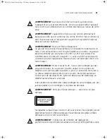
Page 19: ...afety information provided in Appendix A of this guide AVERTISSEMENT Consignes de s curit Avant d installer ou d enlever tout composant du Switch ou d entamer une proc dure de maintenance lisez les in...

Page 20: ...UTION Ensure that the ventilation holes are not obstructed When deciding where to position the Switch ensure that Cabling is located away from sources of electrical noise such as radios transmitters a...

Page 21: ...te high levels of AC noise for example air conditioning units and laser printers Rack mounting The Switch is 1U high and will fit in most standard 19 inch racks CAUTION Disconnect all cables from the...

Page 22: ...itch into the 19 inch rack and secure with suitable screws not provided Ensure that ventilation holes are not obstructed 6 Connect network cabling 7 Finally place a unit information label on the unit...

Page 23: ...r outlet 3 The Power Self Test LED will flash green for approximately 60 seconds 4 When the unit is ready the Power Self Test LED lights green The Switch powers up and runs through its Power On Self T...

Page 24: ...The Switch has no ON OFF switch the only method of connecting or disconnecting mains power is by connecting or disconnecting the power cord Choosing the Correct Cables All of the ports on the Switch a...

Page 25: ...The following section describes the use of SFP transceivers in your Switch SFP transceivers are hot insertable and hot swappable You can remove them from and insert them into any SFP port without havi...

Page 26: ...ot recommended If the SFP transceiver is invalid it will not be recognized by the Switch Use the following sequence of steps to activate the SFP ports 1 Hold the transceiver so that the fiber connecto...

Page 27: ...rectly Refer to LEDs on page 14 for more information Removing an SFP Transceiver If you wish to remove a 3Com transceiver it is not necessary to power down your Switch 1 Disconnect the cable from the...

Page 28: ...28 CHAPTER 2 INSTALLING THE SWITCH DUA1750 0AAA01 book Page 28 Friday December 5 2003 10 24 AM...

Page 29: ...to improve the efficiency of the Switch and therefore the overall performance of your network This chapter explains the initial set up of the Switch and the different methods of accessing the manageme...

Page 30: ...the Switch IP Information is automatically configured See page 31 Do you want to manually configure the IP information Connect to a front network port and use the Web Interface or Command Line Interf...

Page 31: ...to allocate static IP addresses Static IP addresses are necessary to ensure that the Switch is always allocated the same IP information For most installations 3Com recommends that you configure the Sw...

Page 32: ...elf with an appropriate IP address instead of you having to manually reconfigure the Switch If you use the automatic IP configuration method you need to discover the automatically allocated IP informa...

Page 33: ...is whilst the Switch is offline that is before you connect the Switch to a network or whilst the Switch is online that is connected to a network Pre requisites A workstation with terminal emulation so...

Page 34: ...port settings to which you have connected the cable The settings should be set to match the default settings for the Switch which are 19 200 baud 8 data bits no parity 1 stop bit no hardware flow con...

Page 35: ...ompt enter manual The screen prompts you to enter IP information 4 Enter the IP address subnet mask and gateway IP address for the Switch The screen displays a summary of the information entered If us...

Page 36: ...on provided on the CD ROM that accompanies your Switch to discover the automatically allocated IP information 1 Connect your Switch to the network 2 Power up the Switch and wait for two minutes 3 Laun...

Page 37: ...ttach the female connector on the cable to the male connector on the console port of the Switch b Tighten the retaining screws on the cable to prevent it from being loosened c Connect the other end of...

Page 38: ...rectly the top level menu of the command line interface is displayed as shown in the example in Figure 11 Figure 11 Example top level command line interface menu 4 At the Select menu option prompt ent...

Page 39: ...t Each Switch has a command line interface CLI that allows you to manage the Switch from a workstation either locally via a console port connection see Figure 12 or remotely over the network see Figur...

Page 40: ...etwork Refer to Setting Up SNMP Management on page 43 Setting Up Command Line Interface Management This section describes how you can set up command line interface management using a local console por...

Page 41: ...our IP information has been entered correctly and the Switch is powered up 4 To open a Telnet session via the DOS prompt enter the IP address of the Switch that you wish to manage in the following for...

Page 42: ...d on your browser These features are enabled on a browser by default You will only need to enable them if you have changed your browser settings Web Management Over the Network To manage a Switch usin...

Page 43: ...3Com Network Supervisor application that is provided on the CD ROM that accompanies your Switch to provide SNMP management for your Switch If you use 3Com Network Supervisor it automatically loads th...

Page 44: ...he default passwords using either The gettingStarted command on the CLI or The Security Device User Modify operation on the web interface For more information about default users and passwords refer t...

Page 45: ...Indicated by LEDs Solving Hardware Problems Solving Communication Problems Solving Software Upgrade Problems If you experience a problem that is not listed here it may be included in the Support secti...

Page 46: ...matically disabled You can verify this by checking that the Port Status LED is flashing Green Yellow This could be due to loop back failure If a port fails the Switch passes its Power On Self Test and...

Page 47: ...ixed end and not at the auto negotiation end Solving Hardware Problems In the rare event of your Switch unit experiencing a hardware failure refer to the list of suggested solutions below A fan failur...

Page 48: ...eway IP address within the Switch is the same as the IP address of the router The Switch s IP address has been entered correctly in your network management application such as 3Com Network Supervisor...

Page 49: ...the Internet you may use any arbitrary IP address as long as it is not being used by another device on your network 3Com suggests you use addresses in the range 192 168 0 0 to 192 168 255 255 with a...

Page 50: ...50 CHAPTER 4 PROBLEM SOLVING DUA1750 0AAA01 book Page 50 Friday December 5 2003 10 24 AM...

Page 51: ...ents pr sentent des consignes que vous devez respecter pour garantir votre s curit personnelle Vous devez respecter attentivement toutes les consignes Nous vous demandons de lire attentivement les con...

Page 52: ...U S A and Canada The cord set must be UL approved and CSA certified The minimum specification for the flexible cord is No 18 AWG Type SV or SJ 3 conductor The cord set must have a rated current capac...

Page 53: ...for connection to the telecommunications system WARNING RJ 45 Ports These are shielded RJ 45 data sockets They cannot be used as standard traditional telephone sockets or to connect the unit to a tra...

Page 54: ...met un branchement sur une entr e d appareil EN60320 CEI 320 Etats Unis et Canada Le cordon doit avoir re u l homologation des UL et un certificat de la CSA Le cordon souple doit respecter titre minim...

Page 55: ...l appellation Neutre et avec raccordement direct la terre masse AVERTISSEMENT Points d acc s RJ 45 Ceux ci sont prot g s par des prises de donn es Ils ne peuvent pas tre utilis s comme prises de t l...

Page 56: ...senstecker mu eine passende Konfiguration f r einen Ger teeingang gem EN60320 IEC320 haben VORSICHT Die Netzsteckdose mu in der N he des Ger ts und leicht zug nglich sein Die Stromversorgung des Ger t...

Page 57: ...VORSICHT Faseroptikanschl sse Optische Sicherheit Niemals ein bertragungslaser betrachten w hrend dieses eingeschaltet ist Niemals direkt auf die Faseransnchl sse und auf die Faserkabelenden schauen...

Page 58: ...58 APPENDIX A SAFETY INFORMATION DUA1750 0AAA01 book Page 58 Friday December 5 2003 10 24 AM...

Page 59: ...B PIN OUTS Null Modem Cable 9 pin to RS 232 25 pin PC AT Serial Cable 9 pin to 9 pin DUA1750 0AAA01 book Page 59 Friday December 5 2003 10 24 AM...

Page 60: ...nal Data C 5 Not assigned Bidirectional Data C 6 Receive Data Bidirectional Data B 7 Not assigned Bidirectional Data D 8 Not assigned Bidirectional Data D Pin Number 10BASE T 100BASE TX 1000BASE T Por...

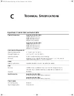
Page 61: ...humidity non condensing Standards EN60068 to 3Com schedule Package testing paras 2 1 2 2 2 30 and 2 32 Operational testing paras 2 1 2 2 2 30 and 2 13 Safety Agency Certifications UL60950 EN60950 CSA...

Page 62: ...FC 1213 Bridge MIB RFC 1493 RMON MIB II RFC 2021 Remote Monitoring MIB RFC 1757 MAU MIB RFC 2239 Terminal Emulation Telnet RFC 854 Protocols Used for Administration UDP RFC 768 IP RFC 791 ICMP RFC 792...

Page 63: ...neers are available to manage your installation with minimal disruption to your network Expert assessment and implementation services are offered to fill resource gaps and ensure the success of your n...

Page 64: ...telephone e mail and internet access to technical support and repair services To access these services for your region use the appropriate telephone number URL or e mail address from the list below Yo...

Page 65: ...888 9469 10800 61 00137 or 021 6350 1590 or 00800 0638 3266 800 6161 463 080 333 3308 00801 611 261 001 800 611 2000 You can also obtain support in this region using the following e mail apr_technica...

Page 66: ...alvador Trinidad and Tobago Uruguay Venezuela Virgin Islands AT T 800 998 2112 57 1 657 0888 AT T 800 998 2112 1 800 998 2112 571 657 0888 01 800 849CARE AT T 800 998 2112 AT T 800 998 2112 54 11 4894...

Page 67: ...eatures 12 I installing the Switch 19 prerequisites 20 IP addressing registered 49 IP configuration 31 L LEDs 14 logging in as a default user 43 M MAC address of the Switch 22 management methods 39 pr...

Page 68: ...number 22 automatic setup 36 console port 15 16 dimensions 61 Ethernet address 22 features 12 installation 19 20 MAC address 22 power socket 16 powering up 23 product name 22 rack mounting 21 serial n...

Page 69: ...d receiver are on different branch circuits If necessary the user should consult the dealer or an experienced radio television technician for additional suggestions The user may find the following boo...

Page 70: ...DUA1750 0AAA01 book Page 70 Friday December 5 2003 10 24 AM...

Reviews: