background image

Installation Manual 
H3C S9500 Series Routing Switches 

Chapter 3  Installing the Switch


3-24 


  Note: 

The installation method described below is based on an N68 cabinet. The 

installation procedure is only for your reference if you use a non-N68 

cabinet. 


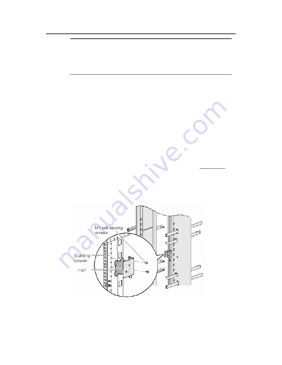
A fiber management tray (FMT) is installed in a cabinet for winding 

redundant fibers between the S9500 and other devices. 

1) Preparations 

The installation prerequisites are as follows: 

z


The cabinet is fixed well. 

z


The device has been installed completely. 

The installation involves the following materials: 

z


FMT 

z


M5×10 self-tapping screws (two screws for one FMT) 

2) Installation 

Procedure 

To install the fiber management tray, proceed as shown in 

Figure 3-24

z


Align the fiber management tray and the installation holes on the 

column of the cabinet. 

z


Use a Phillips screwdriver to fix each fiber management tray with two 

M5×10 self-tapping screws. 


Figure 3-24 

Install FMTs 

Summary of Contents for S9505

Page 1: ...H3C S9500 Series Routing Switches Installation Manual Hangzhou H3C Technologies Co Ltd http www h3c com Manual Version T2 08048H 20071025 C 2 03 Product Version S9500 CMW520 R2127 ...

Page 2: ...m InnoVision and HUASAN are trademarks of Hangzhou H3C Technologies Co Ltd All other trademarks that may be mentioned in this manual are the property of their respective owners Notice The information in this document is subject to change without notice Every effort has been made in the preparation of this document to ensure accuracy of the contents but all statements information and recommendation...

Page 3: ...anual Organization H3C S9500 Series Routing Switches Installation Manual is organized as follows Chapter Contents 1 Product Overview Introduces the appearance architecture and system features of the S9500 series 2 Preparing for Installation Lists the preparations and precautions for the installation 3 Installing the Switch Details the installation of the chassis PSUs boards and cable connection fo...

Page 4: ...are grouped in square brackets and separated by vertical bars One or none is selected x y Alternative items are grouped in braces and separated by vertical bars A minimum of one or a maximum of all can be selected x y Optional alternative items are grouped in square brackets and separated by vertical bars Many or none can be selected 1 n The argument s before the ampersand sign can be entered 1 to...

Page 5: ...eader be careful Improper operation may cause data loss or damage to equipment Note Means a complementary description Environmental Protection This product has been designed to comply with the requirements on environmental protection For the proper storage use and disposal of this product national laws and regulations must be observed ...

Page 6: ... Overview 1 1 1 1 Introduction 1 1 1 2 Physical Structure 1 1 1 2 1 Chassis and Slots 1 2 1 2 2 Backplane 1 5 1 2 3 Power System 1 6 1 2 4 PoE Power Supply 1 8 1 2 5 Fan Tray 1 10 1 3 Switching and Routing Processing Unit 1 11 1 4 Line Processing Unit 1 12 1 5 Service Board 1 14 1 6 System Specifications 1 14 ...

Page 7: ...orts 20 10GE ports 240 FE electrical ports or 100 FE optical ports z S9508 This model provides a switching capacity of up to 960 Gbps It allows for the concurrent wire speed forwarding on 384 GE ports 32 10GE ports 384 FE electrical ports or 160 FE optical ports z S9508V This model provides a switching capacity of up to 960 Gbps It allow for the concurrent wire speed forwarding on 384 GE ports 32 ...

Page 8: ... PSUs are hot swappable 1 2 1 Chassis and Slots I S9505 1 SRPU slots 2 LPU slots 3 Cable management bracket 4 PSUs 5 PoE power entry module 6 Fan tray Figure 1 1 Front view of the S9505 z The S9505 chassis provides seven slots in its board area The top two accommodate SRPUs which can operate in 1 1 redundancy mode the remaining five accommodate LPUs service boards z At the bottom of the chassis is...

Page 9: ... 1 2 Front view of the S9508 z The S9508 chassis provides ten slots in its board area The middle two accommodate SRPU modules the remaining eight accommodate LPUs service boards z At the bottom of the chassis is the power area that contains one PoE power entry module and two PSUs The switch supports both AC and DC power inputs So you can select AC or DC PSUs as needed z On the right of the chassis...

Page 10: ...s the remaining eight accommodate LPU service boards z At the bottom of the chassis is the power area that contains one PoE power entry module and two PSUs The switch supports both AC and DC power inputs So you can select AC or DC PSUs as needed z Above the power area is the air filter which can be removed from the chassis in the case of replacement or regular cleaning z On the top of the chassis ...

Page 11: ...PUs service boards z At the bottom of the chassis is the power area that contains one PoE entry module and two PSUs The switch supports both AC and DC power inputs So you can select AC or DC PSUs as needed z On the right of the chassis is the fan area that contains two vertical fan trays The fans draw air in from the left and exhaust air from the right 1 2 2 Backplane The backplane of the S9500 se...

Page 12: ... 3 Power System Note z The S9500 series support both AC and DC power inputs So you can choose AC or DC PSUs as needed z The S9500 series support 1 1 power supply redundancy z The PSUs of the S9500 series are hot swappable The power system is at the bottom of the chassis In the PSU slots you can insert either two AC PSUs or two DC PSUs The PSUs are cooled by the built in fans which draw air into th...

Page 13: ...NEPS3500 A enclosure 1 sub PSU no redundancy 1 NEPS3500 A enclosure 2 sub PSU 1 1 redundancy 1200 W 90 V to 180 V 1800 W 180 V to 264 V 1 NEPS3500 A enclosure 2 sub PSU no redundancy 2 NEPS3500 A enclosure 3 sub PSU 2 1 redundancy 2 NEPS3500 A enclosure 4 sub PSU 2 2 redundancy backup 2400 W 90 V to 180 V 3500 W 180 V to 264 V NEPS3500 A 2 NEPS3500 A enclosure 3 sub PSU no redundancy 2 NEPS3500 A ...

Page 14: ...ble z The S9500 series can supply power to remote PDs through Ethernet electrical ports on the LPUs Each LPU can simultaneously supply power to up to 48 PDs with the maximum distance of 100 m 328 1 feet z Each Ethernet port can deliver up to 15 4 W to its PD z The S9500 series determine whether to deliver power to a newly detected PD according to the following condition If the remaining PoE power ...

Page 15: ... controller One Rectifiers NP2500UAC Two NP2500UACs required one redundant NP2500UAC optional NP2500UAC is hot swappable AC accessories Three AC inputs and switches Three AC voltage detection circuits Input voltage range 90 to 264 VAC DC accessories A single DC output with a max output power of 4500 W 220 V 2400 W 110 V The external PoE power system has the monitoring function It provides one RS23...

Page 16: ... Green ON OFF PSU shutdown or PSU running trouble Alarm LED ALM Red OFF ON Loss of AC input power under voltage or over voltage input over voltage output output short circuit or PSU fault 1 2 5 Fan Tray z The S9505 uses one 25 W fan tray which contains four 120 120 25 4 mm 4 7 4 7 1 0 in DC fan units z The S9508 uses one 35 W fan tray which contains six 120 120 25 4 mm 4 7 4 7 1 0 in DC fan units ...

Page 17: ...ting normally ALM Red ON The fan tray is faulty 1 3 Switching and Routing Processing Unit SRPUs serve as the core of the S9500 series They mainly have the following functions z Route calculation and forwarding table maintenance z Integrating crossbar switching fabric to accomplish service exchange between different boards z Providing system configuration and monitoring functions which allows the s...

Page 18: ... the SRPU is applicable to the switch SRP2N s forwarding capacity is twice the SRP1N s 1 4 Line Processing Unit The following LPUs are available Table 1 8 LPUs available LPU Suffix User interface LSB1FP20 B0 CA0 20 100 Mbps SFP LC optical ports LSB1F32G B0 CA0 4 1000 Mbps SFP LC optical ports and 32 auto sensing 10 100 Mbps RJ 45 ports LSB1FT48 B0 48 auto sensing 10 100 Mbps RJ 45 electrical ports...

Page 19: ...ts LSB1GT48L DB0 48 auto sensing 10 100 1000 Mbps RJ 45 electrical ports wire speed LSB1P4G8 CA0 8 1000 Mbps SFP LC optical ports and 4 OC 3c SFP LC POS optical ports LSB1GT8P CA0 4 1000 Mbps SFP LC optical ports and 8 auto sensing 10 100 1000 Mbps RJ 45 ports LSB1XP2 B0 CA0 CB0 DB0 DC0 2 10GBase R XFP LC 10GBase W XFP LC optical ports LSB1XP4 B0 CA0 DB0 4 10GBase R XFP LC 10GBase W XFP LC optical...

Page 20: ...etailed specifications for the SRPUs LPUs and service boards visit the website at www h3c com 1 6 System Specifications The following table summarizes the physical specifications of the S9500 series Table 1 9 Technical specifications of the S9500 series Item S9505 S9508 S9508V S9512 Dimensions H W D 486 436 450 mm 19 1 17 2 17 7 in 619 436 450 mm 24 4 17 2 17 7 in 888 436 450 mm 35 17 2 17 7 in 75...

Page 21: ...P1N 7 LSB1SRP2N 5 LSB1SRP2N 7 LSB1SRP1N4 LSB1SRP1N7 LSB1SRP2N4 LSB1SRP2N7 Number of LPU slots 5 8 8 12 User interface z 10 100 1000BASE TX RJ45 z 10 100BASE TX RJ45 z 1000BASE X SFP LC z 100BASE FX SFP LC z 10GBASE R XENPAK SC z 10GBASE R W XFP LC z OC 3c SFP LC POS z OC 48c SFP LC POS z OC 192c SFP LC POS z OC 48c SFP LC RPR z OC 192c SFP LC RPR Operating temperature 0 C to 45 C 32 F to 113 F Ope...

Page 22: ...ng Installation Site 2 3 2 2 1 Temperature Requirements 2 3 2 2 2 Humidity Requirements 2 3 2 2 3 Cleanness Requirements 2 4 2 2 4 EMS Requirements 2 5 2 2 5 Grounding Requirements 2 5 2 2 6 Power Supply Requirements 2 5 2 2 7 Space Requirements 2 6 2 3 Cabinet Mounting Requirements 2 7 2 3 1 Cabinet Requirements 2 7 2 3 2 Requirements of Supports 2 8 2 4 Requirements of Power Distribution Box 2 9...

Page 23: ...area such as ungrounded power extension cables missing safety grounds and moist floors z Locate the emergency power off switch in the room before installation Shut the power off at once in case accident occurs z Unplug all the external cables including power cords before moving the chassis z Better not maintain the equipment alone when it has been powered z Never assume but check each time that po...

Page 24: ...e external cables including power cords before moving the chassis z Do not move the switch alone z Move the switch slowly and stably Keep in step with your partner and balance your bodies when moving the switch Caution You can only hold the handles at both sides of the chassis when moving the switch but not the plastic panel of the chassis the handle of the fan frame the handle of the PSUs the han...

Page 25: ...emperature requirements Temperature Range Operating temperature 0 C to 45 C 32 F to 113 F Storage temperature 40 C to 70 C 40 F to 158 F The higher the temperature the greater the damage it will do to the switch Long lasting high temperature will speed up the aging process of the insulating materials greatly lower the reliability of the switch and therefore affect its service life seriously Cautio...

Page 26: ...ult in the poor contact of the connector or metal contact point This happens more frequently when indoor relative humidity is low which will not only shorten the service life of the switch but also cause communication failure The required specifications on dust content and particle diameter in an equipment room are shown in the following table Table 2 3 Limitation on dust content and particle diam...

Page 27: ...ound of the switch from the grounding device of the power supply equipment or lightning protection grounding device as far as possible z Keep the switch far away from the radio launcher radar launcher and high frequency devices working in the high current z Adopt electromagnetic shielding if necessary Note If necessary take electromagnetic shielding measures against the interference 2 2 5 Groundin...

Page 28: ... Two 1800W sub PSUs 30 A Table 2 6 Specifications for DC PSUs Specifications Item NEPS1200 D NEPS2000 D NEPS3500 D Model S9505 S9508 S9512 S9508 S9512 Rated voltage range 48 VDC to 60 VDC 48 VDC to 60 VDC 48 VDC to 60 VDC Input voltage range 36 VDC to 72 VDC 36 VDC to 72 VDC 36 VDC to 72 VDC Max input current 25 A 42 A 75 A Max output power 1 200 W 2 000 W 3 500 W 2 2 7 Space Requirements For the ...

Page 29: ...eter high N68 cabinet 600 800 1800 mm or 23 6 31 5 70 9 in z N68 22 model 2 2 meter high N68 cabinet 600 800 2200 mm or 23 6 31 5 86 7 in Note For the procedure of installing and remodeling an N68 cabinet refer to H3C N68 Cabinet Installation and Remodel Introduction You can also install the switch in a 19 inch cabinet provided by other vendors II Weight bearing capacity and power The cabinet must...

Page 30: ...east 15 2 cm 6 0 in is required between the side panels of the cabinet and the switch If the switch is to be installed in a closed cabinet make sure that the cabinet has a good ventilation system 2 3 2 Requirements of Supports 1 The length of supports depends on the cabinet depth 2 You can use supports such as shelf or angles to install the switch into the cabinet The supports must be able to bear...

Page 31: ...he bottom of a power distribution box Figure 2 4 Terminal block structure diagram The terminal block has 21 terminals to connect power cords seven grey terminals seven blue terminals and seven yellow green terminals z The grey terminals from L1 to L7 are output ports for live wire These ports are connected to each other z The blue terminals from N1 to N7 are output ports for neutral wire These por...

Page 32: ... sectional area 16 mm 2 Input Maximum current maximum crimping area 101A 25 mm 2 Output seven loop outputs II Power Distribution Box Appearance Figure 2 5 Front view of the power distribution box Figure 2 6 Top view of the power distribution box Caution Make sure the power cord ports are covered with protection tube such that no wire tailpiece is exposed at any joint III Connect power cords to the...

Page 33: ...binet power distribution box to the system power supply and PoE power supply The three wires of each cable should be respectively connected to the ports L N and PE of the power distribution box Make sure the protection tubes are used and no wire tailpiece is exposed during the connection You should connect power cord 1 to L1 N1 and PE1 power cord 2 to L2 N2 and PE2 and so on The number of power co...

Page 34: ... S9505 chassis 5 PoE power entry module 6 S9505 chassis 7 System power input 8 Interface area on external PoE power supply panel 9 External PoE power supply 10 PoE AC socket 11 17 No 1 to No 7 power cable 18 N68 cabinet 19 Terminal block Figure 2 7 Cable connections on the power distribution box 2 4 2 Installing DC Power Distribution Box I Terminal Block 1 Terminal block structure diagram ...

Page 35: ... blocks are DC input terminal blocks Next to them are two air switches each of which has a through current capacity of 63A On the rightmost side are 9 terminal blocks 6 of which are BGND terminal blocks and the rest are PGND terminal blocks 2 Diagram for connecting terminal blocks 1 Connected to user supplied DC power 2 Connected to the negative terminal of 48 V DC power 3 Connected to the positiv...

Page 36: ...minal block components Table 2 9 illustrates terminal block components Table 2 9 Terminal block components NO Name Quantity 1 End bracket 2 2 Cross connector 3 3 Marker 6 4 Terminal 11 5 Clapboard 7 6 Rail 1 7 Circuit breaker 6 II Installing DC Power Distribution Box To install power distribution box take the following steps 1 Install the DC input terminal blocks and air switches to the cabinet vi...

Page 37: ...ke the air switches to supply power to DC power modules by connecting the lower terminals of the air switches to DC power input terminals and supply voltages to DC power Refer to Figure 2 9 for detail Note that the diameters of the cables need to be 6 mm2 or 10 mm2 5 You can use the BGND and PGND terminal blocks as needed The rightmost PGND terminals must be connected to the cabinet using 6 mm2 ca...

Page 38: ...ouble ring spanner 10 12 or open ended spanner 10 12 Small tools Sharp nose pliers diagonal pliers vices hand held electric drill file handsaw crowbar rubber hammer General tools Auxiliary tools Brush tweezers paper knife hand bellows electric iron solder wire fork ladder Special tools ESD preventive wrist strap cable stripper crimping pliers RJ 45 crimping pliers wire punch down tool Meters Multi...

Page 39: ... 5 1 In a common grounding environment 3 5 3 5 2 In other Grounding Environments 3 5 3 6 Installing a PSU 3 9 3 6 1 Installation Preparation 3 9 3 6 2 Installation Procedure 3 9 3 6 3 Connecting Power Cable s 3 11 3 7 Installing a Board 3 15 3 7 1 Installation Preparations 3 15 3 7 2 Installation Procedure 3 16 3 8 Installing PoE Power Supply 3 16 3 8 1 Installation Procedure 3 17 3 8 2 Installing...

Page 40: ... warning to avoid bodily injury 3 1 Installation Flow Start Confirm installation preparation Confirm installation position Mount the switch in a rack Install the switch on a workbench Install a PSU Install boards Install PoE power supply optional Connect the PGND wire Finish Verify the installation Connect interface cables Figure 3 1 Installation flow 3 2 Confirming Installation Preparation z Make...

Page 41: ... a place near the cabinet 3 3 2 Installing the Cable Management Bracket and Rack Mounting Ears For your convenience a cable management bracket is shipped with the S9500 series Take the following steps to install the cable management bracket 1 Facing the LPU slots of the switch insert the shipped cable management bracket into the left rack mounting ear on which there is a recessed hole for installi...

Page 42: ...the supports and slide it into the cabinet until the rack mounting ears touch against the front square holed columns 2 Fix the rack mounting ears onto the square holed columns with screws Figure 3 3 Install the switch into a standard 19 inch rack 3 3 4 Verifying the Installation After installing the switch into the rack check the items listed in Table 3 1 Table 3 1 Checklist for switch installatio...

Page 43: ...on a clean and stable workbench 3 4 1 Preparations z Make sure that the workbench is sturdy enough to bear the weight of the switch and cables z Make sure that the workbench is flat and well grounded 3 4 2 Procedure Lift the switch onto the workbench with another person Caution Reserve at least 15 2 cm 6 0 in of clearance around the switch for heat dissipation 3 5 Connecting the PGND Wire Caution ...

Page 44: ...he switch on the grounding screw 3 Insert the grounding screw into the grounding hole and screw it down 4 Connect the other end of the PGND wire to the ground bar of the switch as shown in Figure 3 4 Figure 3 4 Connect the PGND wire Note Generally the cabinets installed in equipment rooms are equipped with ground bar In this case you can connect the PGND wire of the switch to the ground bar for it...

Page 45: ... attach one end of the yellow green PGND wire of the switch to a grounding bolt of the ground bar and fasten the captive screws Caution Note that neither the fire hydrant nor lightning rod of a building is suitable for grounding the switch The PGND wire of the switch should be connected to the grounding device in the equipment room For the S9500 series the grounding screw is on the rear panel Conn...

Page 46: ...angle iron steel pipe and the joint should be processed against eroding For the S9500 series the grounding screw is on the rear panel Connect it as illustrated in Figure 3 5 3 4 5 1 2 3 4 5 1 2 1 Rear panel of the switch 2 Grounding screw 3 PGND wire 4 Ground 5 Angle steel steel pipe Figure 3 6 Ground the switch when allowed to bury grounding body nearby z If both ground bar and the conditions for...

Page 47: ... 1 2 3 5 4 3 5 4 1 2 1 Front panel of the switch 2 AC power input 3 3 core AC power cord 4 Transformer 5 Protection earth PE wire Figure 3 7 Ground the switch through the AC PE wire z If no ground bar or condition for burying the grounding body is available a DC powered Ethernet switch can be grounded through the PGND strip of the power distribution frame PDF Caution Make sure the RTN wire is well...

Page 48: ... switch through the PGND strip of the PDF 3 6 Installing a PSU 3 6 1 Installation Preparation z Wear an ESD preventive wrist strap and verify the ESD preventive wrist strap is properly grounded z If there is a filler panel in the position where you will install a PSU remove the filler panel Caution When you move a PSU hold its bottom with one hand Do not move it by just holding its handle Otherwis...

Page 49: ...ng the guide rails until it snaps into the backplane Figure 3 9 Install an AC PSU 3 Fasten the captive screws on both sides of the PSU with a Philips screwdriver and install the removed air filter cover onto the PSU 4 Check that the power switch on the PSU is in the OFF position II Installing NEPS3500 A NEPS3500 A contains two sub PSU slots You can configure one or two 1800 W sub PSUs Follow these...

Page 50: ...de the sub PSU smoothly along the guide rails until it snaps into the backplane 3 Push the handle upward so that the sub PSU moves further inside about 1 cm 0 39 in until the handle locks the sub PSU in place as shown in the rightmost graph in Figure 3 10 Figure 3 10 Install a 1800 W sub PSU 3 6 3 Connecting Power Cable s I Connecting the AC power cord Caution z For lightning protection the AC pow...

Page 51: ...put LED 3 Output LED 4 Fail LED 5 Power switch 6 PSU handle 7 AC power cord Figure 3 11 NEPS1200 A appearance 1 Connector retention clamp 2 Input LED 3 Output LED 4 Fail LED 5 Power switch 6 PSU handle 7 AC power cord Figure 3 12 NEPS2000 A appearance Take the following steps to connect the AC power cord to NEPS3500 A 1 Insert the plug at one end of the AC power cord into the socket on the PSU ...

Page 52: ... with screws A plastic cover plate is installed in front of the terminal block for the sake of connection reliability Caution z Completely power off the switch before connecting the DC power cord z Before removing or installing the DC power cables you need to remove the plastic cover plate Install it after installing removing the DC power cables Take the following steps to connect the DC power cab...

Page 53: ...U and fasten the corresponding fixing screw Connect the other end to the RTN terminal of the power source 4 Connect one end of the cable with PGND OT terminals yellow green to the PGND terminal on the PSU and fasten the corresponding fixing screw Connect the other end to the ground bar of the switch 5 Install the plastic cover plate 1 Terminal block 2 Input LED 3 Output LED 4 Fail LED 5 Power swit...

Page 54: ...es are not equipped with plastic cover plates 3 7 Installing a Board The installation procedures of SRPUs LPUs and service boards are almost the same The following section describes the installation procedure of LPUs 3 7 1 Installation Preparations z Wear the ESD preventive wrist strap making sure that it is properly grounded z Loosen the mounting screws on the blank filler panel where the SRPU is...

Page 55: ...hat is the positioning pins on the ejector levers touch the positioning holes on the chassis 2 Turn the ejector levers towards the front panel to drive the positioning pins into the positioning holes Figure 3 16 Install an LPU 3 Fix the LPU by fastening the mounting screws on the LPU with a Phillips screwdriver 3 8 Installing PoE Power Supply The S9505 S9508 S9512 uses PSE4500 A as an external PoE...

Page 56: ...k the PoE power entry module which is shown in Figure 3 17 Figure 3 17 PoE power entry module 2 Keep the PoE power entry module in the correct letter direction Do not turn it upside down Otherwise you will not be able to fully insert it into the chassis due to mis plug prevention design of the module nor can you fasten the chassis fixing screw Hold the bottom with one hand and the front panel with...

Page 57: ...the cable connection between the external PoE power supply and the S9500 series switch For the installation of the external PoE power supply see the manual accompanying the power supply I Grounding the PoE chassis Follow these steps to ground the PoE chassis 1 Connect the wiring terminal with one M6 hole of the 6 AWG cable to the grounding screw on the rear panel of the switch as shown in Figure 3...

Page 58: ...e blue DC power cable to the NEG terminal of the PoE power entry module and fasten the mounting screw connect the other end to the NEG terminal of the external PoE power supply 3 Connect the PGND OT terminal of the black DC power cable to the RTN terminal of the PoE power entry module and fasten the mounting screw connect the other end to the RTN terminal of the external PoE power supply Caution z...

Page 59: ...nd power cables are routed to the front of the chassis II Rack Mounted switch z The interface cables are bound on the cable management bracket on the left side of the chassis and are routed up or down to pass through the chassis top or the raised floor depending on the available equipment room condition that is signal cables are routed into the chassis either from the cabling racks on the chassis ...

Page 60: ...fer to Appendix B Engineering Labels for Cables 3 9 2 Connecting Console Cable I Introduction Console cable is an 8 core shielded cable At one end of the cable is a crimped RJ 45 connector that is to be plugged into the console port of the switch At the other end of the cable is a DB 9 female connector You can plug it into the 9 pin male serial port on the console terminal The following figure ill...

Page 61: ... switch is to be configured 2 Connect the RJ 45 connector of the console cable to the console port of the switch Figure 3 22 Connect the console cable Note The PC serial port is not hot swappable so you are not allowed to insert or remove the console cable into or from the PC serial port When connecting the console cable first connect the DB9 end to the PC serial port and then the RJ45 end to the ...

Page 62: ...efer to Figure 3 21 and Table 3 3 II Connecting AUX cable 1 Plug the RJ 45 connector of the AUX cable into the AUX port of the switch 2 Plug the DB 9 male connector at the other end into the serial port of the modem 3 9 4 Connecting Network Cables I Introduction to RJ 45 connector The 10 100 1000Base T ports of the S9500 series support MDI MDI X auto sensing They are connected to category 5 shield...

Page 63: ...er devices 1 Preparations The installation prerequisites are as follows z The cabinet is fixed well z The device has been installed completely The installation involves the following materials z FMT z M5 10 self tapping screws two screws for one FMT 2 Installation Procedure To install the fiber management tray proceed as shown in Figure 3 24 z Align the fiber management tray and the installation h...

Page 64: ...ion between optical channels which makes the optical system debugging and maintenance more convenient and the transit dispatching of the system more flexible Among various fiber connectors only the LC connector is introduced here Figure 3 25 LC connector III Precautions z Be sure to install the dust cover if the optical port is not connected to a fiber connector z Some invisible rays may be emitte...

Page 65: ...ace the filleting radius must be not less than 2 mm When passing through a metallic board hole or bending along the acute side of mechanical parts the fiber must wear jackets or cushions z Insert and remove a plug with care Never exert a fierce force to the fiber or plug otherwise the plug may be damaged or the fiber may be broken Never pull press or extrude the fiber fiercely For the allowed maxi...

Page 66: ... the power before checking the installation in case of bodily injury and device damage After installing the switch verify the installation against the following list For the successful installation all items must be normal Table 3 5 Installation checklist Item Normal Abnormal Description Console cable PGND wire Power cables SRPUs LPUs service boards Fan tray s PSUs ...

Page 67: ...he Switch 4 1 4 1 Setting Up Configuration Environment 4 1 4 1 1 Setting Up Configuration Environment 4 1 4 1 2 Setting Terminal Parameters 4 1 4 2 Powering On the Switch 4 4 4 2 1 Checklist for Switch Power On 4 4 4 2 2 Powering on the Switch 4 5 4 2 3 Verifying after Power on Recommended 4 5 4 2 4 Boot Interface 4 5 ...

Page 68: ...Figure 4 1 Connect a PC to the switch with a Console cable 4 1 2 Setting Terminal Parameters This section describes how to set the terminal parameters 1 Start the PC and run the terminal emulation program The following uses a PC running Windows XP HyperTerminal as an example 2 Select Start Programs Accessories Communications HyperTerminal to access the HyperTerminal window Click in the window to s...

Page 69: ...e of the new connection in the Connection Description dialog box and click OK The system displays the interface shown in Figure 4 3 Select a port in the Connect using drop down list Figure 4 3 Select a port for the HyperTerminal connection 4 Set serial port parameters Set the bits per second to 9600 data bits to 8 parity to none stop bits to 1 and flow control to none ...

Page 70: ...s Routing Switches Chapter 4 Commissioning the Switch 4 3 Figure 4 4 Set serial port parameters 5 Click OK after setting the serial port parameters to enter the HypterTerminal window as shown in Figure 4 5 Figure 4 5 HyperTerminal window ...

Page 71: ...ct VT100 for terminal emulation and click OK Note You are recommended to select the Windows keys option button Figure 4 6 Set the terminal emulation parameters 4 2 Powering On the Switch 4 2 1 Checklist for Switch Power On Before powering on the switch make sure that z The interface cables power cables and the grounding cable are correctly connected z The power outlet voltage is the same as the on...

Page 72: ...R on the switch 4 2 3 Verifying after Power on Recommended To ensure the configuration works that you will make on the switch you are recommended to check the switch after powering it on to make sure that z The cooling system is working In this case you can hear the noise caused by fan rotation and feel that there is air exhausted out z All the system LEDs on the SRPUs function normally 4 2 4 Boot...

Page 73: ... B to enter Boot Menu 0 Auto booting Boot from primary file Boot from cf S9500 app Initialize CF card done Loading from CF card done Booting from CF card Be sure the BaudRate is 9600bps Decompress Image OK Starting at 0x10000 User interface con0 is available Press ENTER to get started The above prompt information appears when the switch completes its boot sequence Press Enter to begin configuring ...

Page 74: ...s 5 2 5 1 4 Troubleshooting LPUs 5 3 5 2 Hardware Maintenance 5 4 5 2 1 Replacing a PSU 5 4 5 2 2 Replacing and Cleaning the PSU Air Filter 5 6 5 2 3 Replacing and Cleaning the Chassis Air Filter 5 8 5 2 4 Replacing and Installing a Card 5 9 5 2 5 Replacing the Fan Tray 5 10 5 3 Software Upgrade 5 13 5 3 1 Recommended Upgrade Procedure 5 13 5 3 2 Local Loading through Boot Menu 5 14 5 3 3 Local or...

Page 75: ...this case you should check whether z The power system is working normally z The SRPU is working normally z The Console cable has been connected to the Console port on the SRPU If no problem has been found in the above checking the symptom is very likely to be caused by the errors listed below z The Console cable is not connected to the right serial port that is the port in use is not the one confi...

Page 76: ...this case switch off the power supply loosen the captive screws on the PSU push the PSU into the chassis a little bit tighten the captive screws and switch on the power supply to check that the normal state is resumed z The Input LED green and Output LED green are OFF In this case check that the power cords are connected correctly the power cords are in good condition and the power switch has been...

Page 77: ...eated z All the cables connecting the fan tray and the backplane have been correctly connected and are in good condition z The fans are working normally z The rotation of the fans has not been blocked z The blank filler panels have been inserted into those LPU slots 5 1 4 Troubleshooting LPUs The S9500 series provide LPUX LEDs on the SRPU for the user to observe the state of these LPUs Note z For ...

Page 78: ...ty with electricity Do not touch any exposed wires terminals or any parts of the product marked with a dangerous voltage label to avoid bodily injury z The PSUs of the S9500 series are hot swappable Before removing a PSU you must turn off its power switch z If you do not want to install a PSU insert a blank filler panel into the PSU slot for dust proofing I Removing a PSU other than NEPS3500 A The...

Page 79: ...separated from the backplane refer to Figure 5 2 2 Hold the handle of the sub PSU with one hand and the bottom with the other hand and gently pull the sub PSU out of the chassis along the guide rails Remove the AC power enclosure 1 Move the power switch on the PSU to the OFF position if it is in the ON position 2 Remove the bail latch and unplug the power cord 3 Remove the captive screws on the bo...

Page 80: ...r way even though they have different shapes Caution You are strongly recommended to clean the air filter semi monthly to guarantee adequate ventilation I Removing and cleaning the PSU air filter 1 Clutch the air filter by the upper and lower edges with your index finger and the thumb and pull the air filter out gently 2 Take the black air filter mesh off 3 Wash the mesh using clean water and air ...

Page 81: ...4 Remove the air filter from the AC PSU II Installing the PSU air filter 1 Check that the black mesh has been nested in the air filter cover as shown in Figure 5 5 Figure 5 5 Install the PSU air filter 1 2 Clutch the air filter cover by the upper and lower edges with your index finger and thumb and push it inside the PSU with an even force as shown in Figure 5 6 ...

Page 82: ...508V contains a chassis air filter For the S9500 series except the S9508V the procedure for replacing and cleaning installing the chassis air filter is the same I Removing cleaning and installing the chassis air filter of the S9505 S9508 S9512 z To remove and cleaning the chassis air filter follow the procedure below 1 Loosen the captive screws at the top and bottom of the air filter with a Philli...

Page 83: ...he upper and lower edges using your index finger and the thumb and remove the air filter cover gently 3 Pull out the nested black air filter mesh 4 Wash the air filter mesh using water and then air dry it Take care not to rub the air filter mesh when you wash it z To install the chassis air filter follow the procedure below 1 Nest the black air filter mesh into the air filter cover 2 Hold the air ...

Page 84: ...ray Caution z Do not touch exposed wires terminals or the switch parts where dangerous voltage warning is given to avoid bodily injury z Install a new fan tray soon after removing the old one to ensure the normal working of the switch For the S9500 series except the S9508V the procedure for replacing installing the fan tray is the same Note z The fan tray is delivered together with the switch and ...

Page 85: ...ing switch pull the fan tray half way out of the chassis to disconnect the power and wait till the fans stop rotating before pulling it out completely Considering that the fans may be still rotating avoid stretching your hands into the fan tray Figure 5 8 Replace the fan tray 1 2 Slide the new fan tray smoothly along the guide rails until it fits into the chassis with its plug fully touching the s...

Page 86: ...ear an ESD preventive wrist strap Caution When you replace the fan tray on an operating switch pull the fan tray half way out of the chassis to disconnect the power and wait till the fans stop rotating before pulling it out completely Considering that the fans may be still rotating avoid stretching your hands into the fan tray 2 Press the button using your thumb and slide the fan tray out of the c...

Page 87: ...il it fits into the chassis with its plug fully touching the socket inside the chassis Figure 5 11 Replace the S9508V fan tray 2 Note The S9508V fan tray has no captive screws and is fixed by two locks 5 3 Software Upgrade 5 3 1 Recommended Upgrade Procedure You can load the software through command line interface CLI and Boot menu 1 Local loading using Boot menu z Loading using XModem and through...

Page 88: ...hen the host software to be loaded does not match the current Boot ROM z You can load only Boot ROM and host software of SRPUs through the Boot menu To load Boot ROM of LPUs use the CLI mode 5 3 2 Local Loading through Boot Menu Caution Never hot plug the CF card after you enter the Boot ROM menu After replacing the CF card you must reboot the SRPU Otherwise the CF card cannot work properly I Boot...

Page 89: ...is 000f e222 ce4d Press Ctrl B to enter Boot Menu 0 Password Note To enter the Boot menu you must press Ctrl B within five seconds after the appearance of the prompt Press Ctrl B to enter Boot menu Otherwise the program decompression process will begin To access the Boot menu after the Switch enters the program decompression process you need to restart the Switch Enter the correct Boot ROM passwor...

Page 90: ...erwise you have to upgrade it during host program upgrade When loading the host program through the Boot menu you must configure correct attributes of the serial interface as shown in Figure 5 12 Otherwise the HyperTerminal does not respond Figure 5 12 Attribute settings of HyperTerminal serial interface II Upgrading software through console port XModem z Brief introduction to XModem XModem a type...

Page 91: ...file to SDRAM through serial interface and boot 2 Download file to Flash through serial interface 3 Download file to CF card through serial interface 4 Modify serial interface boot parameter 0 Return to main menu Enter your choice 0 4 4 2 Enter 4 in the serial interface submenu and press Enter to access the following interface for setting the parameters of the downloading serial interface 1 9600 d...

Page 92: ...l before setting the baud rate and connect the terminal after finishing the work z Since the software Release 2100 and later is quite large in size you have to download it into the CF card 5 Select a right place to store the downloaded file as needed For example enter 3 at the prompt displayed in the last step to download the file into the CF card of the switch press Enter and the system will disp...

Page 93: ...gh serial interface 3 Download file to CF card through serial interface 4 Modify serial interface boot parameter 0 Return to main menu Enter your choice 0 4 III Upgrading software through management Ethernet port TFTP z Introduction to TFTP Trivial file transfer protocol TFTP is well suited to the file transfer between a server and a client that do not need complex interaction In TFTP the transmis...

Page 94: ...t menu 4 Enter 5 in the Boot menu Press Enter and the system will access the download application program menu ETHERNET SUBMENU 1 Download file to SDRAM through ethernet interface and boot 2 Download file to Flash through ethernet interface 3 Download file to CF card through ethernet interface 4 Modify ethernet interface boot parameter 0 Return to main menu Be sure to select 4 to modify boot param...

Page 95: ...in menu Enter your choice 0 4 2 7 At the prompt displayed in step 6 select a place for the downloaded file for example select 3 to download the file to the CF card and press Enter The system will display the following information on the terminal screen Attached TCP IP interface to fei0 Attaching network interface lo0 done boot device fei0 unit number 0 processor number 0 host name 9500 file name 9...

Page 96: ... port In this case you should know the IP address of the PC At the same time connect the Switch to an external PC that can be the same one that contains the desired file via the Console port 2 Run FTP Server on the PC connected to the management upgrade Ethernet port specify the path of the upgrading file and set the login username and password 3 Run the terminal emulation program on the PC connec...

Page 97: ...TP server on a local PC provided you have configured username and password and have set the correct file directory Suppose IP address of the PC is 10 10 110 1 Log on to the switch using Telnet or through the Console port to send host program to the switch using FTP Suppose that the main boot file is SWITCH002 app the active host program is SWITCH001 app the Boot ROM program is SWITCHbtm btm You ca...

Page 98: ...oot of board 6 at this time is flash SWITCH001 app The app to boot of board 7 at the next time is flash SWITCH002 app The app to boot of board 7 at this time is flash SWITCH001 app H3C reboot Caution z You must reboot the switch using the reboot command to validate the host program z Make sure that you have saved other configurations before reboot Otherwise they might not survive a reboot z Power ...

Page 99: ...ng the configuration you must check the operating status of the LPU Do not save the configuration during the LPU reboot Otherwise the configuration you want to save may be lost IV LPU program loading fails or you cannot register for a long period z Check LPU type to see if this type is supported on the current host program z Check whether the LPU Boot ROM program matches the host program before up...

Page 100: ...Installation Manual H3C S9500 Series Routing Switches Table of Contents i Table of Contents Appendix A Cable Management A 1 A 1 Correct Use of Labels A 1 A 2 Cable Management Requirements A 1 ...

Page 101: ...nd radius of the cable cannot be less than 5 times of its diameter at the place where it is led out of the connector z Different cables power cord signal cable PGND wire etc should be cabled and bound separately rather than together in the cabinet If they are close to each other you can cable them in cross shape For parallel cabling the space between power cord and signal cable should be no less t...

Page 102: ...e III z The spare cables or excessive cable parts should be folded and bound and placed at a right place in the cabinet or on the cabling channel A right place refers to the place where the cables will not affect the operation of the device or impair the device or be damaged z The power cords cannot be tied on the guides of any mobile components z Reserve some redundancy for the cables connecting ...

Page 103: ...as to free the terminal and the cable from stress z Do not use tapping screws to fasten the connecting terminals z The power cords of the same type and in the same direction should be bound together and kept neatly and straight The following table lists the requirements in the binding with cable ties Table A 1 Tie binding parameters Cable bundle diameter mm Space between bundles mm 10 80 to 150 10...

Page 104: ... Writing Labels B 5 B 1 5 Affixing Labels B 5 B 1 6 Information Carried on Labels B 8 B 1 7 Remarks B 8 B 2 Engineering Labels for Ethernet Cables B 9 B 3 Engineering Labels for Optical Fibers B 10 B 3 1 Labels for the Fiber that Connects Two Devices B 10 B 3 2 Labels for the Fiber that Connects the Device and the ODF B 12 B 4 Engineering Labels for Power Cables B 13 B 4 1 Labels for DC Power Cabl...

Page 105: ...net The signal cables include external cables of alarm box Ethernet cables optical fibers trunk cables and subscriber cables excluding the antenna feeders Note In case there is special requirement from the user of the equipment on the description method of the labels the labels should be printed accordingly However this must be stated in the self check report B 1 Introduction to Labels B 1 1 Mater...

Page 106: ...iding line is 1 5mm 0 6mm in size with the color of PONTONE 656c light blue The cut dotted line helps to fold the label when affixing it to the cable and its size is 1 0mm 2 0mm There is a mark TO upside down in the figure at the lower right corner of the label The mark is used to identify the opposite end of the cable on which the label is affixed II Label for power cables The label for power cab...

Page 107: ...irectly modify the contents on the template and the following should be observed z The settings of centered characters direction and fonts should not be changed z When there are too many characters to be filled in zoom out the characters but make sure the printouts are clear and legible II Cells merging on the template To merge the cells you should first recover the table structure if gridlines ar...

Page 108: ...justing the page setup is as follows 1 Select the menu item File Page Setup 2 Select the Margins tab page 3 Select Left for Gutter Position 4 Set Header and Footer as 0 and adjust the values of Top Bottom Left and Right After the page setup has been made correct save it for future use This page setup is only necessary in the first time you use the template to print the labels IV Requirements on fe...

Page 109: ...contaminate the label and blur the words Note The delivered marker has two nibs Make sure to use the smaller nib to write the labels For the sake of easy recognition and good looking the font in handwriting should be close to the standard typeface as much as possible Table B 1 shows the standard typeface Table B 1 Standard typeface for handwriting 0 1 2 3 4 5 6 7 8 9 A B C D E F G H I J K L M N O ...

Page 110: ...the connector on the signal cable In special cases for example to avoid cable bent or affecting other cables other positions are allowed to affix the labels 1 Stick the label to the proper position on the cable fold the narrow part of the label according to the directions shown in Figure B 5 Stick side Fold to right Cable Stick side Fold down Cable Figure B 5 Stick the label onto proper position o...

Page 111: ...cable tie The label should be stuck to the rectangular flute and should be stuck to only one side of the identification plate Make sure to affix the labels on the same side of the identification plates The cable ties are bundled at 2cm from the connectors and other positions are allowed in special circumstances Cable ties should be bundled on both ends of a cable After the bundling the finished id...

Page 112: ...e B 9 Printed parts on the label for signal cables Seen from the cabling end of the equipment the text part of the label is on the right side of the cable The side with TO that is facing outside carries the location information of the opposite end and the other side carries the location information of the local end Therefore the information in Area 1 at one end is the same as the information in Ar...

Page 113: ... Valid location number of the terminal device onsite If the cable is connected to a router in a cabinet the serial numbers of the cabinet the frame and the Ethernet interface of the router should be specified for example B02 03 12 If the cable is connected to the Network Management Station NMS specific location of the NMS should be given In VAS products the information provided on the labels is di...

Page 114: ... Port 05 Slot 10 Frame 03 of the cabinet on Row A Column 01 in the machine room B02 03 12 indicates that the opposite end of the Ethernet cable is connected with Ethernet Port 12 Frame 03 of the cabinet on Row B Column 02 in the machine room B 3 Engineering Labels for Optical Fibers These labels are affixed to the optical fibers that connect the optical interfaces on the boards in a frame or on th...

Page 115: ... receiving interface T optical transmitting interface MN cabinet number B frame number C physical slot number D optical interface number The meanings are the same as above When the local device and the opposite end device are not in the same machine room MN can be the name of the machine room MN B C D R T R optical receiving interface T optical transmitting interface II Example of the label Figure...

Page 116: ...e MN cabinet number For example A01 B frame number Numbered in bottom up order with two digits for example 01 C physical slot number Numbered in top down and left right order with two digits for example 01 D optical interface number Numbered in top down and left right order with two digits for example 05 MN B C D R T R optical receiving interface T optical transmitting interface MN row number and ...

Page 117: ...on plates on cable ties I Meaning of the label Table B 5 shows the information carried on the labels for the DC power cables Table B 5 Information on labels affixed to the DC power cables Content Meaning MN BC 48V1 MN BC 48V2 MN BC BGND MN BC PGND MN BC BC is written right under MN On the loaded cabinet side only MN is used to identify the cabinet On the power cabinet side MN identifies the row an...

Page 118: ... 13 1 indicates the label on the loaded cabinet side which carries the information about the position of the cable on the power distribution box 2 indicates the label on the distribution box side which carries the information about the position of the cable on the loaded cabinet side On the loaded cabinet side the label marked with A01 B08 48V2 on the cable indicates that the cable is 48V2 DC supp...

Page 119: ...ar way B 4 2 Labels for AC Power Cables The labels are affixed to the AC cables that provide power for the cabinets and the protection grounding cables including the POWER PGND and BGND cables The 220V AC cables and related PGND and BGND cables are covered with insulating sheath so the labels only need to contain the words of AC and the cabinet number The labels for AC power cables are affixed to ...

Page 120: ...mple of the labels on the AC power cable In Figure B 14 1 indicates the label on the loaded cabinet side which carries the information about the position of the cable on the power socket 2 indicates the label on the power socket side which carries the information about the position of the cable on the loaded cabinet side On the loaded cabinet side the label marked with A01 AC indicates that the po...

Page 121: ...Installation Manual H3C S9500 Series Routing Switches Table of Contents i Table of Contents Appendix C Installation of Lightning Arrester for AC Power C 1 ...

Page 122: ... cable clips and screws to fasten the lightning arrester for AC power on the cabinet workbench or the wall of equipment room Mainboard Grounding and polarity indicator red On means that the lines are wrongly connected either the ground wire is not well connected or the live and zero lines are wrongly connected Please check the power supply circuit Power switch Normal operation indicator green On m...

Page 123: ...ectly locate the problem whether it is caused because the ground wire of the arrester is not well grounded or because the live and zero wires are connected in reverse direction You may check that in the following way When the red LED is on use a multimeter to examine polarity at the power socket of the arrester If it is same to that of the power socket in the equipment room it means that arrester ...

Reviews: