142
C
HAPTER
4: C
ONFIGURING
P
ATH
B
UILDER
S330/S310 M
ODULES
, P
ORTS
,
AND
A
PPLICATIONS
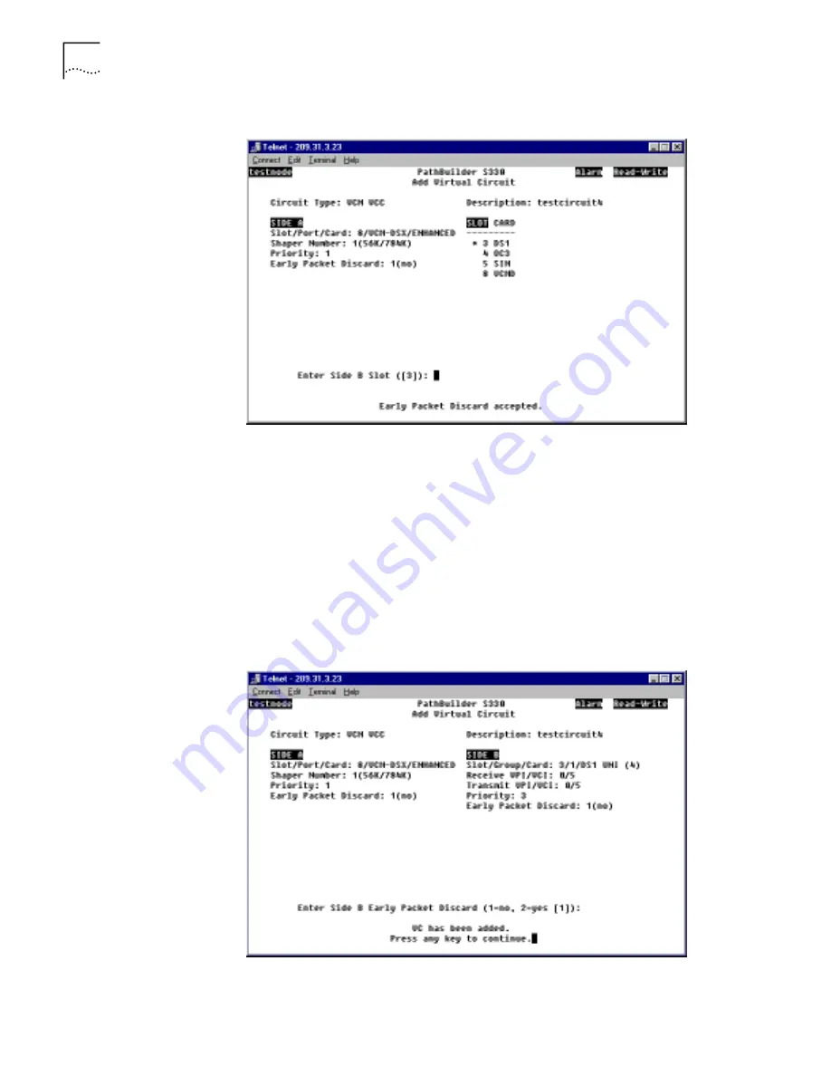
Figure 132
VCM VCC Add Virtual Circuit Screen with Side A Completed
5
Select the slot number corresponding to the module by which you are connected
to the network for side B of the circuit.
6
Repeat steps 3and 4 for side B of the circuit. The following prompt appears at the
bottom of the screen:
Is the above information correct (y/n)?
7
Enter
y
to confirm your configuration. Figure 133 shows a completed VCM VCC
circuit. As shown in the figure, the following message appears at the bottom of
the screen:
VC has been added.
Press any key to continue.
Figure 133
Completed VCM VCC Virtual Circuit
8
Press any key to return to the Virtual Circuit menu.


