


P-873HNU(P)-51B User’s Guide
183
C
H A P T E R
1 4
Interface Group
14.1 Overview
By default, all LAN and WAN interfaces on the VDSL Router are in the same group and can
communicate with each other. Create interface groups to have the VDSL Router assign the IP
addresses in different domains to different groups. Each group acts as an independent network on
the VDSL Router. This lets devices connected to an interface group’s LAN interfaces communicate
through the interface group’s WAN or LAN interfaces but not other WAN or LAN interfaces.
14.2 The Interface Group Screen
You can manually add a LAN interface to a new group. Alternatively, you can have the VDSL Router
automatically add the incoming traffic and the LAN interface on which traffic is received to an
interface group when its DHCP Vendor ID option information matches one listed for the interface
group.
Use the LAN screen to configure the private IP addresses the DHCP server on the VDSL Router
assigns to the clients in the default and/or user-defined groups. If you set the VDSL Router to
assign IP addresses based on the client’s DHCP Vendor ID option information, you must enable
DHCP server and configure LAN TCP/IP settings for both the default and user-defined groups. See
for more information.
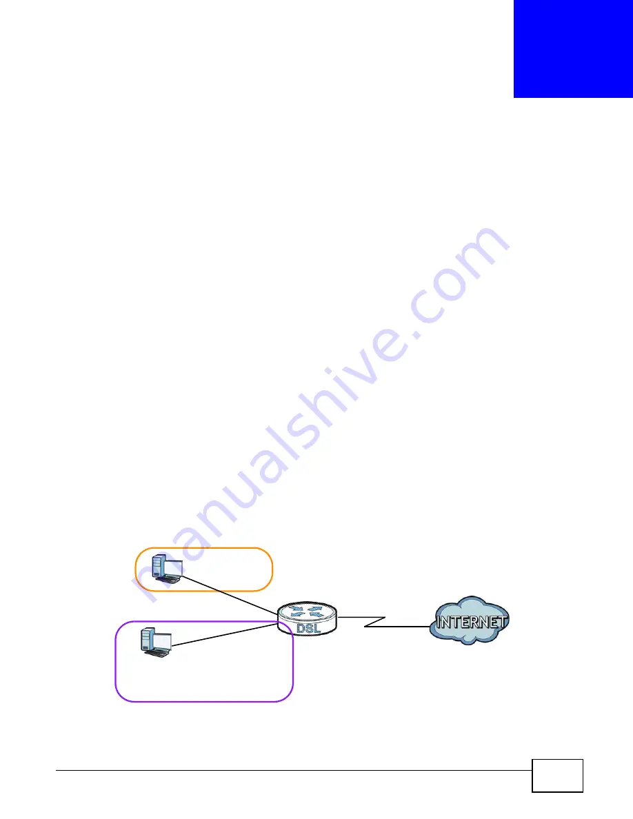
In the following example, the client that sends packets with the DHCP Vendor ID option set to MSFT
5.0 (meaning it is a Windows 2000 DHCP client) is assigned the IP address 192.168.2.2 and uses
the WAN VDSL_PoE/ppp0.1 interface.
Figure 85
Interface Grouping Application
Click Network Settings > Interface Group to open the following screen.
Default: ETH 2~4
192.168.1.x/24
192.168.2.x/24
VDSL_PoE/ppp0.1
eth10.0
DHCP Vendor ID option: MSFT 5.0
Содержание P-873HNU-51B
Страница 4: ...Contents Overview P 873HNU P 51B User s Guide 4...
Страница 13: ...Table of Contents P 873HNU P 51B User s Guide 13 Appendix F Legal Information 329 Index 333...
Страница 14: ...Table of Contents P 873HNU P 51B User s Guide 14...
Страница 15: ...15 PART I User s Guide...
Страница 16: ...16...
Страница 32: ...Chapter 2 The Web Configurator P 873HNU P 51B User s Guide 32...
Страница 57: ...57 PART II Technical Reference...
Страница 58: ...58...
Страница 64: ...Chapter 5 Network Map and Status Screens P 873HNU P 51B User s Guide 64...
Страница 108: ...Chapter 7 Wireless P 873HNU P 51B User s Guide 108...
Страница 132: ...Chapter 9 Static Routing P 873HNU P 51B User s Guide 132...
Страница 152: ...Chapter 10 Quality of Service QoS P 873HNU P 51B User s Guide 152...
Страница 168: ...Chapter 11 Network Address Translation NAT P 873HNU P 51B User s Guide 168...
Страница 182: ...Chapter 13 IGMP P 873HNU P 51B User s Guide 182...
Страница 188: ...Chapter 14 Interface Group P 873HNU P 51B User s Guide 188...
Страница 202: ...Chapter 17 Parental Control P 873HNU P 51B User s Guide 202...
Страница 224: ...Chapter 22 Logs P 873HNU P 51B User s Guide 224...
Страница 234: ...Chapter 25 xDSL Statistics P 873HNU P 51B User s Guide 234...
Страница 238: ...Chapter 26 Users Configuration P 873HNU P 51B User s Guide 238...
Страница 244: ...Chapter 27 Remote Management P 873HNU P 51B User s Guide 244...
Страница 250: ...Chapter 29 Logs Setting P 873HNU P 51B User s Guide 250...
Страница 256: ...Chapter 31 Configuration P 873HNU P 51B User s Guide 256...
Страница 262: ...Chapter 32 Diagnostic P 873HNU P 51B User s Guide 262...
Страница 274: ...Chapter 34 Product Specifications P 873HNU P 51B User s Guide 274...
Страница 310: ...Appendix C Pop up Windows JavaScript and Java Permissions P 873HNU P 51B User s Guide 310...
Страница 324: ...Appendix D Wireless LANs P 873HNU P 51B User s Guide 324...


