


Chapter 8 Connections and LEDs
MS-7206 Hardware Installation Guide
65
MP-7203 DC-DC Power Module
Each MP-7203 DC-DC power module has two terminal blocks which allow you to connect to
two power supplys. Use two wires to connect to each terminal block, one wire for the positive
terminal and one wire for the negative terminal.
"
The current rating of the power wires must be greater than 20 Amps.
"
The power supply to which the MP-7203 connects must have a built-in circuit
breaker or switch to toggle the power.
1
Slide the power switch socket cover down.
2
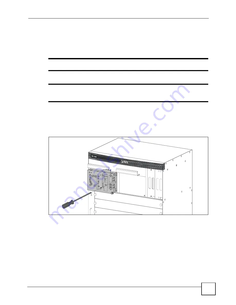
Use a screwdriver to loosen the thumbscrew on the front panel of the power module.
3
Use a screwdriver to loosen the screw on the cover of the terminal block and remove it.
Figure 28
Removing the Terminal Block Cover from the MP-7203 Power Module
4
Grab the handle and slide the module out of the slot slightly untill the screws on the side
of the terminal blocks are exposed.
5
Connect one power wire to the RTN (return) terminal on the MS-7206 power module
and tighten the screw.
6
Connect the other end of the power wire to the positive terminal on the power supply.
7
Connect one power wire to the -48V (input) terminal on the MS-7206 power module and
tighten the terminal screw.
8
Connect the other end of the power wire to the negative terminal on the power supply.
Содержание MS-7206
Страница 2: ......
Страница 8: ...Safety Warnings MS 7206 Hardware Installation Guide 8...
Страница 10: ...Contents Overview MS 7206 Hardware Installation Guide 10...
Страница 14: ...Table of Contents MS 7206 Hardware Installation Guide 14...
Страница 18: ...List of Tables MS 7206 Hardware Installation Guide 18...
Страница 20: ...20...
Страница 36: ...Chapter 3 MI 7248 Specifications MS 7206 Hardware Installation Guide 36...
Страница 40: ...Chapter 4 MI 7248PWR Specifications MS 7206 Hardware Installation Guide 40...
Страница 44: ...Chapter 5 MI 7248TF Specifications MS 7206 Hardware Installation Guide 44...
Страница 45: ...45 PART II Installation and Connections Chassis Installation 47 Installing Cards 51 Connections and LEDs 59...
Страница 46: ...46...
Страница 50: ...Chapter 6 Chassis Installation MS 7206 Hardware Installation Guide 50...
Страница 57: ...Chapter 7 Installing Cards MS 7206 Hardware Installation Guide 57 Figure 20 Install a Power Adaptor Card...
Страница 58: ...Chapter 7 Installing Cards MS 7206 Hardware Installation Guide 58...
Страница 68: ...Chapter 8 Connections and LEDs MS 7206 Hardware Installation Guide 68...
Страница 70: ...70...
Страница 78: ...Chapter 10 Hardware Troubleshooting MS 7206 Hardware Installation Guide 78...
Страница 81: ...81 PART IV Appendices and Index Legal Information 83 Customer Support 87 Index 93...
Страница 82: ...82...
Страница 86: ...Appendix A Legal Information MS 7206 Hardware Installation Guide 86...


