background image

Chapter 20 Configuration: VLAN

GS1900 Series User’s Guide

136

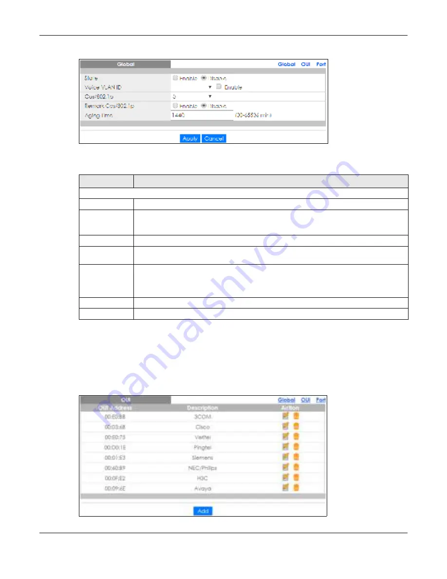
Fig ure  134   

Configuration > VLAN > Voice VLAN > Global

The following table describes the labels in this screen.

20.4.2  The  O UI Sc re e n

Use this screen to view the OUI settings. The maximum number of entries is 16. Modifying the OUI table 
will restart auto detection of OUI process. Click 

C o nfig ura tio n

 > 

VLAN

 > 

Vo ic e  VLAN

 > 

O UI

 to open this 

screen.

Fig ure  135   

Configuration > VLAN > Voice VLAN > OUI

Table 81   Configuration > VLAN > Voice VLAN > Global  

LABEL

DESC RIPTIO N

Global

State

Select 

Ena b le

 to activate the global voice VLAN feature.

Voice VLAN ID

Enter the global voice VLAN ID. It should be a unique VLAN ID in the system and cannot equal 
each port PVID. It is a conflict in configuration if the value equals management VID, MVR VID, 
PVID etc. The allowed range is 1 to 4094.

Cos/802.1p

Displays the 802.1p packet priority field.

Remark Cos/
802.1p

Select to 

Ena b le

 the priority remark function for cos/802.1p.

Aging Time

Enter the voice VLAN secure learning aging time. The allowed range is 10 to 10000000 seconds. 
It is used when security mode or auto detect mode is enabled. In other cases, it will be based 
on hardware aging time. The actual aging time will be situated between the [age_time; 2 * 
age_time] interval.

Apply

Click

 Apply 

to save the changes.

Cancel

Click 

C a nc e l 

to discard the changes.

Содержание GS1900 Series

Страница 1: ...in Details User s Guide GS1900 Series GbE Smart Managed Switch Copyright 2021 Zyxel Communications Corporation IP Address http 192 168 1 1 In band ports User Name admin Password 1234 Version 2 60 Edition 2 02 2021 ...

Страница 2: ...formation in this manual is accurate Note This guide is a reference for a series of products Therefore some features or options in this guide may not be available in your product Note It is recommended you use the Web Configurator to configure the Switch Re late d Doc ume ntation Online Help Click the help link for a description of the fields in the Switch menus More Information Go to https busine...

Страница 3: ... the Switch in this guide Product labels screen names field labels and field choices are all in bold font A right angle bracket within a screen name denotes a mouse click For example Configuration Syste m Information means you first click Configuration in the navigation panel then the Syste m sub menu and finally the Information tab to get to that screen Ic ons Use d in Figure s Figures in this us...

Страница 4: ...or Loop Guard 87 Monitor Multicast 90 Monitor Spanning Tree 94 Monitor LLDP 100 Monitor Security 104 Monitor Management 107 Configuration System 110 Configuration Port 115 Configuration VLAN 128 Configuration MAC Table 140 Configuration Link Aggregation 144 Configuration Loop Guard 150 Configuration Mirror 153 Configuration Time Range Group 156 Configuration Multicast 161 Configuration Spanning Tr...

Страница 5: ... 5 IEEE 802 1Q VLAN Application Example 19 1 2 6 IPv6 Support 20 1 3 Ways to Manage the Switch 20 1 4 Good Habits for Managing the Switch 21 Chapte r 2 Hardware Installation and Conne c tion 22 2 1 Safety Precautions 22 2 2 Installation Scenarios 22 2 3 Desktop Installation Procedure 23 2 4 Wall Mounting 24 2 4 1 Wall mounted Installation Requirement 24 2 5 Rack Mounting 25 2 5 1 Rack mounted Inst...

Страница 6: ...tch 39 Chapte r 4 ZON Utility 40 4 1 Zyxel One Network ZON Utility Screen 40 4 1 1 Requirements 40 4 1 2 Run the ZON Utility 41 Chapte r 5 We b Configurator 45 5 1 Overview 45 5 2 Access 45 5 3 Navigating the Web Configurator 47 5 3 1 Title Bar 47 5 3 2 Navigation Panel 48 Chapte r 6 Ge tting Start 54 6 1 Overview 54 6 1 1 What You Can Do in this Chapter 54 6 2 Getting Start 54 6 2 1 Wizard 55 Par...

Страница 7: ...itor VL AN 76 9 1 Overview 76 9 1 1 What You Can Do in this Chapter 76 9 2 VLAN 76 9 2 1 VLAN 76 9 2 2 Port 77 9 2 3 VLAN Port 78 9 3 Guest VLAN 79 9 4 Voice VLAN 80 Chapte r 10 Monitor MAC T able 82 10 1 Overview 82 10 1 1 What You Can Do in this Chapter 83 10 2 MAC Table 83 Chapte r 11 Monitor L ink Aggre gation 85 11 1 Overview 85 11 1 1 What You Can Do in this Chapter 85 11 2 Link Aggregation ...

Страница 8: ...1 CIST 94 14 2 2 CIST Port 95 14 2 3 MST 96 14 2 4 MST Port 97 14 2 5 STP Statistics 98 Chapte r 15 Monitor L L DP 100 15 1 Overview 100 15 1 1 What You Can Do in this Chapter 100 15 2 LLDP 100 15 2 1 Statistics 100 15 2 2 Remote Information 101 15 2 3 Overloading 102 Chapte r 16 Monitor Se c urity 104 16 1 Overview 104 16 1 1 What You Can Do in this Chapter 104 16 2 Port Security 104 16 3 802 1X ...

Страница 9: ... 19 1 Overview 115 19 1 1 What You Can Do in this Chapter 115 19 2 Port 115 19 2 1 The Port Screen 115 19 2 2 The Port Edit Screen 116 19 3 EEE 117 19 3 1 The EEE Screen 117 19 3 2 The EEE Edit Screen 118 19 4 PoE 119 19 4 1 The Global Screen 119 19 4 2 The Port Screen 120 19 4 3 The PoE Edit Screen 122 19 5 Bandwidth Management 124 19 5 1 The Bandwidth Control Screen 124 19 5 2 The Port Rate Edit...

Страница 10: ...erview 140 21 1 1 What You Can Do in this Chapter 140 21 2 MAC Table 140 21 2 1 The Static MAC Screen 140 21 2 2 The Static MAC Add Screen 141 21 2 3 The Filtering MAC Screen 141 21 2 4 The Filtering MAC Add Screen 142 21 2 5 The Dynamic Age Screen 142 Chapte r 22 Configuration L ink Aggre gation 144 22 1 Overview 144 22 1 1 What You Can Do in this Chapter 144 22 2 Link Aggregation 144 22 2 1 The ...

Страница 11: ...n 158 Chapte r 26 Configuration Multic ast 161 26 1 Overview 161 26 2 IGMP 161 26 2 1 The Global Screen 161 26 2 2 The VLAN Screen 162 26 2 3 The Edit IGMP Screen 163 26 2 4 The Router Port Screen 164 26 2 5 The Add or Edit Router Port Screen 164 26 2 6 The Profile Screen 165 26 2 7 The Add or Edit Profile Screen 166 26 2 8 The Throttling Screen 166 26 2 9 The Edit Throttling Screen 167 Chapte r 2...

Страница 12: ...or Edit Screen 186 28 2 8 The MED Port Screen 187 28 2 9 The MED Port Edit Screen 188 Chapte r 29 Configuration QoS 190 29 1 Overview 190 29 2 General 190 29 2 1 The Port Screen 190 29 2 2 The Port Edit Screen 191 29 2 3 The Queue Screen 192 29 2 4 The CoS Mapping Screen 193 29 2 5 The DSCP Mapping Screen 194 29 2 6 The IP Precedence Mapping Screen 195 29 3 Trust Mode 196 29 3 1 The Global Screen ...

Страница 13: ...31 3 1 The RADIUS Screen 210 31 3 2 The RADIUS Add or Edit Screen 211 31 4 TACACS 212 31 4 1 The TACACS Screen 212 31 4 2 The TACACS Add or Edit Screen 212 Chapte r 32 Configuration Manage me nt 214 32 1 Overview 214 32 2 Syslog 214 32 2 1 The Global Screen 214 32 2 2 The Local Screen 214 32 2 3 The Local Add or Edit Screen 215 32 2 4 The Remote Screen 216 32 2 5 The Remote Add or Edit Screen 216 ...

Страница 14: ...n a server 231 33 1 3 Upgrade the firmware from a file on your computer 232 33 2 Firmware Management 232 33 2 1 Overview 232 33 2 2 Select the Active Image 233 33 3 Backup a Configuration File 234 33 3 1 Overview 234 33 3 2 Back up configuration or log files to a server 235 33 3 3 Back up configuration or log files to your computer 235 33 4 Restore a Configuration File 235 33 4 1 Overview 235 33 4...

Страница 15: ...33 8 1 Overview 242 33 8 2 Reboot the Switch 242 Chapte r 34 T rouble shooting 243 34 1 Power Hardware Connections and LEDs 243 34 2 Switch Access and Login 244 34 3 Switch Configuration 245 Appendix A Customer Support 246 Appendix B Legal Information 252 Inde x 259 ...

Страница 16: ...16 PART I Use r s Guide ...

Страница 17: ... environments Note that the Switch in the figure is just an example Switch and not your actual Switch 1 2 1 PoE Example Applic ation The Switch can supply PoE Power over Ethernet to Powered Devices PDs such as an IP camera a wireless router an IP telephone and a general outdoor router that are not within reach of a power outlet Table 1 GS1900 Series Comparison Table MODEL GS1900 8 GS1900 8HP GS190...

Страница 18: ...ers can share high speed applications on the server To expand the network simply add more networking devices such as switches routers computers print servers and so on Figure 2 Backbone Example Application 1 2 3 Bridging or Fibe r Uplink Example Applic ation The Switch connects different company departments RD and Sale s to the corporate backbone It can alleviate bandwidth contention and eliminate...

Страница 19: ...h s port or connect other switches to the Switch In this example all computers can share high speed applications on the server and access the Internet To expand the network simply add more networking devices such as switches routers computers print servers and so on Figure 4 Gigabit to the Desktop 1 2 5 IEEE 802 1Q VL AN Applic ation Example A VLAN Virtual Local Area Network allows a physical netw...

Страница 20: ...need to be part of VLAN 1 Ports can belong to other VLAN groups too Figure 5 Shared Server Using VLAN Example 1 2 6 IPv6 Support IPv6 Internet Protocol version 6 is designed to enhance IP address size and features The increase in IPv6 address size to 128 bits from the 32 bit IPv4 address allows up to 3 4 x 1038 IP addresses At the time of writing the Switch supports the following features Static a...

Страница 21: ... page 40 1 4 Good Habits for Managing the Switc h Do the following things regularly to make the Switch more secure and to manage the Switch more effectively Change the password Use a password that is not easy to guess and that consists of different types of characters such as numbers and letters Write down the password and put it in a safe place Back up the configuration and make sure you know how...

Страница 22: ...e cables or power cords on the Switch Allow clearance for the ventilation holes to prevent your Switch from overheating This is especially crucial when your Switch does not have fans Overheating could affect the performance of your Switch or even damage it The surface of the Switch could be hot when it is functioning Do NOT put your hands on it You may get burned This could happen especially when ...

Страница 23: ...cted cables Make sure there is a power outlet nearby 3 Make sure there is at least 40 mm of clearance from the bottom to the Switch and make sure there is enough clearance around the Switch to allow air circulation and the attachment of cables and the power cord This is especially important for enclosed rack installations 4 Remove the adhesive backing from the rubber feet 5 Attach the rubber feet ...

Страница 24: ...ark two holes on the wall at the appropriate distance apart for the screws WARNING Be c are ful to avoid damaging pipe s orc able s loc ate d inside the wall whe n drilling hole s for the sc re ws 3 If using screw anchors drill two holes for the screw anchors into the wall Push the anchors into the full depth of the holes then insert the screws into the anchors Do not insert the screws all the way...

Страница 25: ...n slots should not be fac ing up or down as this position is le ss safe 2 5 Rac k Mounting The Switch can be mounted on an EIA standard size 19 inch rack or in a wiring closet with other equipment Follow the steps below to mount your Switch on a standard EIA rack using a rack mounting kit Note Make sure there is enough clearance between each equipment on the rack for air circulation 2 5 1 Rac k mo...

Страница 26: ...f the Switch Figure 7 Attaching the Mounting Brackets GS1900 16 GS1900 24E and GS1900 24EP Figure 8 Attaching the Mounting Brackets GS1900 24 GS1900 24HP GS1900 24HPv2 GS1900 48 and GS1900 48HP GS1900 48HPv2 2 Using a 2 Philips screwdriver install the M3 flat head screws through the mounting bracket holes into the Switch 3 Repeat steps 1 and 2 to install the second mounting bracket on the other si...

Страница 27: ...ch on a Rack GS1900 24 GS1900 24HP GS1900 24HPv2 GS1900 48 and GS1900 48HP GS1900 48HPv2 2 Using a 2 Philips screwdriver install the M5 flat head screws through the mounting bracket holes into the rack Note Make sure you tighten all the four screws to prevent the Switch from getting slanted 3 Repeat steps 1 and 2 to attach the second mounting bracket on the other side of the rack ...

Страница 28: ...nel and rear panel of the Switch and shows you how to make the hardware connections 3 1 Front Pane l Conne c tions The following figures show the front panels of the Switch Figure 11 Front Panel GS1900 8 Figure 12 Front Panel GS1900 8HP Figure 13 Front Panel GS1900 10HP Figure 14 Front Panel GS1900 16 Revision A1 Revision B1 ...

Страница 29: ...Ethe rne t Ports The Switch has 1000Base T auto negotiating auto crossover Ethernet ports In 10 100 1000 Mbps Gigabit Ethernet the speed can be 10Mbps 100 Mbps or 1000 Mbps The duplex mode can be both half or full duplex at 100 Mbps and full duplex only at 1000 Mbps An auto negotiating port can detect and adjust to the optimum Ethernet speed 10 100 1000 Mbps and duplex mode full duplex or half dup...

Страница 30: ...rating fibe r module s c onne c tors HANDL ING All transc e ive rs are static se nsitive T o pre ve nt damage from e le c trostatic disc harge ESD it is re c omme nde d you attac h an ESD pre ve ntive wrist strap to your wrist and to a bare me tal surfac e whe n you install or re move a transc e ive r ST ORAGE All module s are dust se nsitive Whe n not in use always ke e p the dust plug on Avoid g...

Страница 31: ...ransceiver 3 Pull out the latch and down to unlock the transceiver latch styles vary Note Make sure the transceiver s latch is pushed all the way down so the transceiver can be pulled out successfully 4 Pull the latch or use your thumb and index finger to grasp the tabs on both sides of the transceiver and carefully slide it out of the slot Note Do NOT pull the transceiver out by force You could da...

Страница 32: ... to change how the L ink ACTLED works Each Ethernet port s LED is changed to act as a PoE Mode LED by pushing the PoE MODE button on the front panel Each Ethernet port s LED is changed back to act as a L ink ACTLED by releasing the PoEMODEbutton on the front panel View the LEDs to ensure proper functioning of the Switch and as an aid in troubleshooting see Section 3 3 on page 37 3 2 Re ar Pane l T...

Страница 33: ...ar Panel GS1900 8HP Figure 31 Rear Panel GS1900 10HP Figure 32 Rear Panel GS1900 16 Figure 33 Rear Panel GS1900 24E Figure 34 Rear Panel GS1900 24EP Figure 35 Rear Panel GS1900 24 Figure 36 Rear Panel GS1900 24HP Figure 37 Rear Panel GS1900 24HPv2 Revision B1 Revision A1 ...

Страница 34: ...t cables must be separate from AC power lines To avoid electric surge and electromagnetic interference use a different electrical conduit or raceway tube trough or enclosed conduit for protecting electric wiring that is 15 cm apart or as specified by your country s electrical regulations Any device that is located outdoors and connected to this product must be properly grounded and surge protected...

Страница 35: ... The grounding terminal of the server rack or on site grounding terminal must also be grounded and connected to the building s main grounding electrode Make sure the grounding terminal is connected to the buildings grounding electrode and has an earth resistance of less than 10 ohms or according to your country s electrical regulations Figure 43 Connecting to the Building s Main Grounding Electrod...

Страница 36: ... power receptacle on the back of the Switch and the other end to the appropriate power source For Switches with a power switch see Table 1 on page 17 use the POWER ON OFF switch to have the Switch power on or off Conne c ting the Powe r Use the following procedures to connect the Switch to a power source after you have installed it in a rack Note Use the included power cord for the AC power connec...

Страница 37: ...Green On Power is supplied to all PoE Ethernet ports Off There is no power supplied 1G SFP Slots Fiber Ports see Section 1 1 on page 17 LNK ACT Green Blinking The system is transmitting receiving to from a 100 1000 Mbps Fiber network On The link to a 100 1000 Mbps Fiber network is up Off The link to a Fiber network is down Table 4 LED Descriptions GS1900 8HP Revision B1 and GS1900 10HP Only L ED C...

Страница 38: ...ESETbutton on the front of the Switch as shown in Section 3 1 on page 28 2 Press the button for more than 6 seconds After releasing the button the SYS LED begins to blink Wait for the Switch to restart the SYS LED will be steady green again This takes up to 2 minutes Note If you want to access the Switch Web Configurator again you may need to change Left Amber On The link to a 10 100 Mbps Ethernet...

Страница 39: ...back to factory defaults Use the RESETbutton to reboot the Switch 3 5 1 Re store Button Press the REST ORE button for more than 6 seconds until the SYS LED begins to blink The Switch will automatically reboot and restore the factory default file See Section 3 3 on page 37 for more information about the LED behavior 3 5 2 Re boot the Switc h Press the RESETbutton to reboot the Switch without turnin...

Страница 40: ...tion of the devices and batch firmware upgrade in it You can download the ZON Utility at www zyxel com and install it on a PC Windows operating system 4 1 1 Re quire me nts Before installing the ZON Utility on your PC please make sure it meets the requirements listed below Ope rating Syste m At the time of writing the ZON Utility is compatible with Windows 7 both 32 bit 64 bit versions Windows 8 b...

Страница 41: ...pport the ZON Utility Click the OK button to close this screen Figure 44 Supported Devices and Versions If you want to check the supported models and firmware versions later you can click the Show information about ZON icon in the upper right hand corner of the screen Then select the Supporte d mode l and firmware ve rsion link If your device is not listed here see the device release notes for ZON...

Страница 42: ...45 ZON Utility Screen 3 Select a network adapter to which your supported devices are connected 4 Click the Go button for the ZON Utility to discover all supported devices in your network Figure 46 Discovery 5 The ZON Utility screen shows the devices discovered ...

Страница 43: ... device using the ZON utility icons Figure 48 Password Prompt The following table describes the icons numbered from left to right in the ZON Utility screen 1 2 3 4 5 6 7 8 9 10 11 12 13 Table 5 ZON Utility Icons ICON DESCRIPT ION 1 IP configuration Change the selected device s IP address 2 Renew IP Address Update a DHCP assigned dynamic IP address 3 Reboot Device Use this icon to restart the selec...

Страница 44: ...escan Use this icon to clear the list and discover all devices on the connected network again 12 Save Configuration Use this icon to save configuration changes to permanent memory on a selected device 13 Settings Use this icon to select a network adapter for the computer on which the ZON utility is installed and the utility language Table 6 ZON Utility Fields L ABEL DESCRIPT ION Type This field di...

Страница 45: ...refox or Google Chrome The recommended minimum screen resolution is 1024 by 768 pixels In order to use the Web Configurator you need to allow Web browser pop up windows JavaScript enabled by default Java permissions enabled by default 5 2 Ac c e ss 1 Make sure your Switch hardware is properly connected See the Quick Start Guide 2 Browse to https 192 168 1 1 The L ogin screen appears Figure 49 The ...

Страница 46: ...click Apply to save your changes Table 7 Web Configurator Password Users SNMP L ABEL DESCRIPT ION User This is the default administrator account with the admin user name You cannot change the default administrator user name Old Password Type the existing system password 1234 is the default password when shipped New Password Enter your new system password New Password Confirm Retype your new system...

Страница 47: ...owing functions Apply Click Apply to save your changes to the Switch s run time memory The Switch loses these changes if it is turned off or loses power so use the Sa ve link on the top navigation panel to save your changes to the non volatile memory when you are done configuring Cancel Click Canc e l to begin configuring this screen afresh Table 7 Web Configurator Password Users SNMP continued L ...

Страница 48: ...open screens to configure Switch features The following sections introduce the Switch s navigation panel menus and their screens Figure 54 Navigation Panel Ge tting Start Getting Start displays general device information system status system resource usage and interface status For details on Getting Start features see Chapter 6 on page 54 Logout Click this to log out of the Web Configurator Help C...

Страница 49: ...ports PoE Displays PoE status Bandwidth Management Displays egress global burst and port rate for individual Switch ports Storm Control This link takes you to a screen that displays broadcast filters VLAN This link takes you to screens where you can see port based or 802 1Q VLAN depending on what you configured in the Switch Setup menu You can also see a protocol based VLAN or a subnet based VLAN ...

Страница 50: ... Configuration Menu Screens Summary FOL DER OR L INK T AB FUNCT ION System This link takes you to a screen where you can configure general identification information and time settings for the Switch IP IPv4 This link takes you to a screen where you can enable an IPv4 interface and configure the IPv4 settings on the Switch IPv6 This link takes you to a screen where you can enable an IPv6 interface ...

Страница 51: ...tion Link Aggregation This link takes you to screen where you can logically aggregate physical links to form one logical higher bandwidth link Global Configure global settings LAG Management Configure LAG management settings LAG Port Configure LAG port settings LACP Port Configure LACP port settings Loop Guard This link takes you to a screen where you can configure protection against network loops...

Страница 52: ...apping settings DSCP Mapping Configure DSCP mapping settings IP Precedence Mapping Configure IP precedence mapping settings Trust Mode Global Configure global settings Port Configure port settings Security Configure port security protected port 802 1X and DoS settings Port Security Global Configure global settings Port Configure port settings Protected Port Configure protected port settings 802 1X...

Страница 53: ...P settings HTTPS Configure HTTPS settings Users Configure users settings Remote Access Control This link takes you to a screen where you can configure global and profile settings Table 11 Maintenance Menu Screens Summary FOL DER OR L INK T AB FUNCT ION Firmware Upload Manage upload settings Management Manage dual image and images information Configuration Backup Manage backup configuration Restore...

Страница 54: ...screen is the first thing you see when you log into the Switch It also appears every time you click the Ge tting Start icon in the navigation panel The Ge tting Start displays general device information system status system resource usage and interface status in widgets Figure 55 Getting Start The following table describes the labels in this screen Table 12 Getting Start L ABEL DESCRIPT ION Refres...

Страница 55: ...this Switch Revision This field displays the hardware revision number of this Switch Serial Number This field displays the serial number of this Switch MAC Address Range This field displays the MAC addresses used by the Switch Each physical port or wireless radio has one MAC address The first MAC address is assigned to the Ethernet LAN port the second MAC address is assigned to the first radio and...

Страница 56: ...tory default subnet mask is 255 255 255 0 Gateway Type the IP address of the default outgoing gateway in dotted decimal notation for example 192 168 1 254 DNS DNS Domain Name System is for mapping a domain name to its corresponding IP address and vice versa Enter a domain name server IP address in order to be able to use a domain name instead of an IP address NTP Network Time Protocol This field d...

Страница 57: ... specifies the network number portion of an IP address The factory default subnet mask is 255 255 255 0 Gateway Type the IP address of the default outgoing gateway in dotted decimal notation for example 192 168 1 254 DNS DNS Domain Name System is for mapping a domain name to its corresponding IP address and vice versa Enter a domain name server IP address in order to be able to use a domain name i...

Страница 58: ...able After clicking Next the tag VLAN setting screen appears Figure 60 Getting Start VLAN 2 Step 2 Tag VLAN Setting Table 16 Getting Start VLAN 1 Step 1 Create VLAN L ABEL DESCRIPT ION Create VLAN ID 1 4094 Type a number between 1 and 4094 to create a VLAN ID Edit VLAN ID Select from the drop box a VLAN ID Next Click Ne xt to show the next screen ...

Страница 59: ...N ID This field displays the VLAN identification number Tag Ports belonging to the specified VLAN tag all outgoing frames transmitted Untag Ports belonging to the specified VLAN do not tag all outgoing frames transmitted Previous Click Pre vious to show the previous screen Next Click Ne xt to show the next screen Table 18 Getting Start VLAN 3 Step 3 Finish L ABEL DESCRIPT ION Currently VLAN ID Thi...

Страница 60: ...ish screen appears Figure 63 Getting Start QoS 2 Step 2 Finish Table 19 Getting Start QoS 1 Step 1 QoS Quality of Service L ABEL DESCRIPT ION Highest Click and drag icons located on the left to desired preference Medium Click and drag icons located on the left to desired preference Low Click and drag icons located on the left to desired preference Next Click Ne xt to show the next screen ...

Страница 61: ...ults Previous Click Pre vious to show the previous screen Finish Review the information and click Finish to create the task Table 21 Getting Start Link aggregation 1 Step 1 Link aggregation L ABEL DESCRIPT ION Group 1 Click and drag icons located on the left to desired preference Group 2 Click and drag icons located on the left to desired preference Group 3 Click and drag icons located on the left...

Страница 62: ...k aggregation 2 Step 2 Finish L ABEL DESCRIPT ION Group 1 Displays summary results Group 2 Displays summary results Group 3 Displays summary results Group 4 Displays summary results Group 5 Displays summary results Group 6 Displays summary results Group 7 Displays summary results Group 8 Displays summary results Previous Click Pre vious to show the previous screen Finish Review the information and...

Страница 63: ...63 PART II T e c hnic al Re fe re nc e ...

Страница 64: ...ed over the network The factory default IP address is 192 168 1 1 The subnet mask specifies the network number portion of an IP address The factory default subnet mask is 255 255 255 0 7 2 1 IPv4 Use this screen to view the Switch s IPv4 information Click Monitor Syste m IP IPv4 to open this screen Figure 66 Monitor System IP IPv4 The following table describes the labels in this screen Table 23 Mo...

Страница 65: ... 1 254 DNS Server 1 DNS Domain Name System is for mapping a domain name to its corresponding IP address and vice versa This field displays a domain name server IP address enabling the use of a domain DNS Server 2 DNS Domain Name System is for mapping a domain name to its corresponding IP address and vice versa This field displays a domain name server IP address enabling the use of a domain Managem...

Страница 66: ...rmation System Information L ABEL DESCRIPT ION System Name This field displays the descriptive name of the Switch for identification purposes System Location This field displays the geographic location of the Switch for identification purposes System Contact This field displays the person in charge of the Switch for identification purposes ...

Страница 67: ...atus port counters and bandwidth utilization The PoE screen Section 8 3 on page 71 displays PoE The Bandwidth Manage me nt screen Section 8 4 on page 73 displays bandwidth control The Storm Control screen Section 8 5 on page 74 displays port settings of the Switch 8 2 Port Use this screen to view Switch port settings 8 2 1 Status Use this screen to view the Switch s port statistics Click Monitor P...

Страница 68: ...port State This is port admin setting state Link Status This field displays Up Down or Not Pre se nt It displays Up when the port is linked up or Down when it is not When no any physical port is binding with this group it displays Not Pre se nt Speed View the speed of the Ethernet connection on this port Duplex View the duplex mode of the Ethernet connection on this port FlowCtrl Status A concentr...

Страница 69: ...s the mode Port 1 Interface mib Counters iflnOctets This field displays the iflnOctets iflnUcastPkts This field displays the iflnUcastPkts iflnNUcastPkts This field displays the iflnNUcastPkts ifInDiscards This field displays the ifInDiscards ifOutOctets This field displays the ifOutOctets ifOutUcastPkts This field displays the ifOutUcastPkts ifOutNUcastPkts This field displays the ifOutNUcastPkts...

Страница 70: ...SymbolErrors dot3ControlInUnkownOpcodes This field displays the dot3ControlInUnkownOpcodes dot3lInPauseFrames This field displays the dot3lInPauseFrames dot3lOutPauseFrames This field displays the dot3lOutPauseFrames Port 1 RMON mib Counters etherStatsDropEvents This field displays the etherStatsDropEvents etherStatsOctets This field displays the etherStatsOctets etherStatsPkts This field displays...

Страница 71: ...uipment PSE because it provides a source of power through its Ethernet ports and each device that receives power through an Ethernet port is a Table 28 Monitor Port Port Bandwidth Utilization L ABEL DESCRIPT ION Bandwidth Utilization 1Gbps This field displays the 1Gbps 100Mbps This field displays the 100Mbps 10Mbps This field displays the 10Mbps Link down This field displays the link down Refresh ...

Страница 72: ...ield displays the power management mode used by the Switch whether it is in Classific ation or Consumption mode Total Power W This field displays the total power the Switch can provide to the connected PoE enabled devices on the PoE ports The total power of GS1900 10HP is 77 W and GS1900 8HP is 70 W Consuming Power W This field displays the total amount of power the Switch is currently supplying t...

Страница 73: ... which a data packet leaves for both ports An ingress port is an incoming port that is a port through which a data packet enters Click Monitor Port Bandwidth Manage me nt Bandwidth Control to access this screen Figure 76 Monitor Port Bandwidth Management Bandwidth Control Each field is described in the following table Table 30 Monitor Port Bandwidth Management Bandwidth Control L ABEL DESCRIPT ION...

Страница 74: ...Enabling this feature reduces broadcast multicast and or unicast packets in your network You can specify limits for each packet type on each port Click Monitor Port Storm Control to access this screen Figure 77 Monitor Port Storm Control Ingress RateLimit Kbps View the maximum bandwidth allowed in kilobits per second Kbps for the incoming traffic flow on a port Egress RateLimit Kbps View the maxim...

Страница 75: ...displays the state Broadcast pps Displays how many broadcast packets the port receives in pps Unknown Multicast pps Displays how many unknown multicast packets the port receives in pps Unknown Unicast pps Displays how many unknown unicast packets the port receives in pps Action Displays the action the device takes when a limit is reached The following options are available Drop drop the packet Shu...

Страница 76: ...efore a user will not see the printers and hard disks of another user on the same network VLAN also increases network performance by limiting broadcasts to a smaller and more manageable logical broadcast domain In traditional switched environments all broadcast packets go to each and every individual port With VLAN all broadcasts are confined to a specific broadcast domain 9 1 1 What You Can Do in...

Страница 77: ...N VLAN L ABEL DESCRIPT ION VLAN VLAN ID This is the VLAN identification number VLAN Name Displays a descriptive name for the VLAN for identification purposes VLAN Type Displays a type for the VLAN for identification purposes Table 33 Monitor VLAN VLAN Port L ABEL DESCRIPT ION Port Port This field displays the port number PVID This is the port VLAN identification number A PVID Port VLAN ID is a tag...

Страница 78: ...N VL AN VL AN Port to access this screen Figure 80 Monitor VLAN VLAN VLAN Port Accept Frame Type This field displays the type that is accepted by the frame Specifies the type of frames allowed on a port Choices are All T a g Only and Untag Only All accepts all untagged or tagged frames on this port This is the default setting T ag Only accepts only tagged frames on this port All untagged frames wi...

Страница 79: ...ssword can still access the port but traffic from the user is forwarded to the guest VLAN That is unauthenticated users can have access to limited network resources in the same guest VLAN such as the Internet The rights granted to the Guest VLAN depends on how the network administrator configures switches or routers with the guest network feature Figure 81 Guest VLAN Example Use this screen to vie...

Страница 80: ...iguration for voice traffic as required therefore ensuring the transmission priority of voice traffic and voice quality Use this screen to view Switch global and port voice VLAN settings for voice traffic Click Monitor VL AN Voic e VL AN to access this screen Table 35 Monitor VLAN Guest VLAN L ABEL DESCRIPT ION Guest VLAN State This field displays the state of global guest VLAN Port Port This fiel...

Страница 81: ...State This field displays the state of a port Voice VLAN ID This is the voice VLAN identification number Cos 802 1p This displays the packet s 802 1p priority field Remark Cos 802 1p This field displays the state of the cos 802 1p Aging Time 30 65536 min Displays the time interval from 30 to 65536 in minutes Port Port This field displays a port number State This field displays the state of a port ...

Страница 82: ...ee the following figure 1 The Switch examines a received frame and learns the port from which this source MAC address came 2 The Switch checks to see if the frame s destination MAC address matches a source MAC address already learned in the MAC T able If the Switch has already learned the port for this MAC address then it forwards the frame to that port If the Switch has not already learned the po...

Страница 83: ...e L ABEL DESCRIPT ION MAC Table MAC Address This is the MAC address of the device from which this incoming frame came VLAN Displays a type for the VLAN for identification purposes Port This is the port from which the above MAC address was learned View This link takes you to a screen where you can view the MAC address and VLAN ID of a device attach to a port You can also view what kind of MAC addre...

Страница 84: ...he MAC address is dynamic learned by the Switch or static manually entered in the Static MAC Forwarding screen Port This is the port from which the above MAC address was learned Total Entries Displays the number of total entries Table 37 Monitor MAC Table continued L ABEL DESCRIPT ION ...

Страница 85: ...the fewer available ports you have A trunk group is one logical link containing multiple ports The Switch supports both static and dynamic link aggregation Note In a properly planned network it is recommended to implement static link aggregation only This ensures increased network stability and control over the trunk groups on your Switch 11 1 1 What You Can Do in this Chapte r The L ink Aggre gat...

Страница 86: ...x value Name This field displays the name Type This field displays the type Link Status This field displays the status of the link It displays Up when the port is linked up or Down when it is not When no any physical port is binding with this group it displays NotPre se nt Active Member Displays if this member is an active member of a trunk Standby Member Displays if this member is an standby memb...

Страница 87: ...will receive its own broadcast messages that it sends out as they loop back It will then re broadcast those messages again The following figure shows port N on switch A connected to switch B Switch B is in loop state When broadcast or multicast packets leave port N and reach switch B they are sent back to port N on A as they are rebroadcast from B Figure 87 Switch in Loop State The loop guard feat...

Страница 88: ...f the loop guard probe packet is also shown In this example the probe packet is sent from port N and returns on another port As long as loop guard is enabled on port N The Switch will shut down port N if it detects that the probe packet has returned to the Switch Figure 89 Loop Guard Network Loop 12 1 1 What You Can Do in this Chapte r The L oop Guard screen Section 12 2 on page 88 displays loop g...

Страница 89: ... Each field is described in the following table Table 39 Monitor Loop Guard L ABEL DESCRIPT ION Loop Guard Port This field displays a port number Status This field displays the status Time Left sec This field displays the amount of time left in seconds Action This field displays the action ...

Страница 90: ...is not used to carry user data Refer to RFC 1112 RFC 2236 and RFC 3376 for information on IGMP versions 1 2 and 3 respectively 13 1 1 What You Can Do in this Chapte r The IGMP screen Section 13 2 on page 90 displays Vlan statistics group and router 13 2 IGMP Use this screen to view Switch various multicast features 13 2 1 VL AN Use this screen to view the Switch s IGMP VLAN Click Monitor Multic as...

Страница 91: ...se in seconds for the time interval Last Member Query Count Displays the number of count Interval sec Displays the in seconds for the time interval Querier Allows the Switch to send IGMP General Query messages to the VLANs with the multicast hosts attached Status This field displays the entry as querier or non querier Version This field displays the entry querier version IP This field displays the...

Страница 92: ...ld displays the total amount of report RX General Query RX This field displays the total amount of general query RX Group Spec Query RX This field displays the total amount of group spec query RX Source Spec Query RX This field displays the total amount of source spec query RX Leave TX This field displays the total amount of leave TX Report TX This field displays the total amount of report TX Gene...

Страница 93: ...plays the group IP address Member Ports This field displays the member ports Life sec Displays life in seconds for the time interval Total Entries This field displays the number of total entries Clear Click Cle ar to delete the dynamic groups Refresh Click Re fre sh to reload the page Table 43 Monitor Multicast IGMP Router L ABEL DESCRIPT ION IGMP Router VLAN ID Displays the identification for the...

Страница 94: ...e r The Spanning T re e screen Section 14 2 on page 94 displays CIST CIST port MST MST port STP statistics 14 2 Spanning T re e Use this screen to view Switch spanning tree settings 14 2 1 CIST Use this screen to view the Switch s spanning tree CIST instance Click Monitor Spanning T re e CISTto access this screen Figure 96 Monitor Spanning Tree CIST Each field is described in the following table T...

Страница 95: ...s the lowest cost to the root among the bridges connected to the LAN Root Port On each bridge the bridge communicates with the root through the root port The root port is the port on this Switch with the lowest path cost to the root the root path cost If there is no root port then this Switch has been accepted as the root bridge of the spanning tree network Remaining Hops This field displays the n...

Страница 96: ...lowest cost to the root among the bridges connected to the LAN Edge Port Operation An edge port changes its initial STP port state from blocking state to forwarding state immediately without going through listening and learning states right after the port is configured as an edge port or when its link status changes P2P MAC Operation This field displays the state of the P2P MAC operation Port Role...

Страница 97: ...oughout the network from the device that generates the topology change Table 46 Monitor Spanning Tree MST L ABEL DESCRIPT ION Table 47 Monitor Spanning Tree MST Port L ABEL DESCRIPT ION MST Port MST ID This is the unique identifier for this MST Select a number from the drop down menu to display results Port This field displays the port number MSTI ID A VLAN can be mapped to a specific Multiple Spa...

Страница 98: ...In STP a longer delay is required as the device that causes a topology change first notifies the root bridge and then the root bridge notifies the network Both RSTP and STP flush unwanted learned addresses from the filtering database In RSTP the port states are Discarding Learning and Forwarding Note In this user s guide STP refers to both STP and RSTP Use this screen to view the Switch s spanning...

Страница 99: ...ield displays the configuration BDPUs received TCN BDPUs Received This field displays the TCN BDPUs received MSTP BDPUs Received This field displays the Multiple Spanning Tree Protocol MSTP BDPUs received Configuration BDPUs Transmitted This field displays the configuration BDPUs transmitted TCN BDPUs Transmitted This field displays the TCN BDPUs transmitted MSTP BDPUs Transmitted This field displ...

Страница 100: ...pte r The L L DP screen Section 15 2 on page 100 displays statistics remote information and overloading 15 2 L L DP This link takes you to a screen where you can view LLDP on the Switch LLDP allows a network device to advertise its identity and capabilities on the local network It also allows the device to maintain and store information from adjacent devices which are directly connected to the net...

Страница 101: ...ge Outs This field displays the number of age outs Clear Click Cle ar to clear statistics Refresh Click Re fre sh to reload the page LLDP Port Statistics Port This field displays the port number TX Frames Total This field displays the total number of TX LLDP frames RX Frames Total This field displays the total number of RX LLDP frames RX Frames Discarded This field displays the number of discarded...

Страница 102: ...ion L ABEL DESCRIPT ION Remote Device Local Port This field displays the local port Chassis ID Subtype This field displays the chassis ID subtype Chassis ID This field displays the chassis ID Port ID Subtype This field displays the port ID subtype Port ID This field displays the port ID System Name This field displays the descriptive name of the Switch for identification purposes Time to Live This...

Страница 103: ...andatory TLVs This field displays how many bytes used by mandatory TLVs MED Capabilities This field displays how many bytes used by MED capabilities MED Location This field displays how many bytes used by MED location MED Network Policy This field displays how many bytes used by MED network policy MED Extended Power via MDI This field displays how many bytes used by MED extended power through MDI ...

Страница 104: ...rt and authenticated hosts 16 2 Port Se c urity Port security allows only packets with dynamically learned MAC addresses and or configured static MAC addresses to pass through a port on the Switch The Switch can learn up to 8K MAC addresses in total with no limit on individual ports system total MAC address entry is 8K Static MAC address still can be configured when port security is enabled the fu...

Страница 105: ...r Security Port Security L ABEL DESCRIPT ION Port Security Status This field displays the status of global control information Port Port This field displays a port number Status This field displays the status of port based control information Max MAC Entry Number Displays the designated maximum number of allowed MAC entries The maximum MAC entry number can be learned for individual ports Current A...

Страница 106: ...sts Each field is described in the following table Table 53 Monitor Security 802 1X Port L ABEL DESCRIPT ION Port Status Port This label shows the port you are viewing Status This field displays status of the port Table 54 Monitor Security 802 1X Authenticated Hosts L ABEL DESCRIPT ION Authenticated Hosts User Name This field displays the name of a user Port This label shows the port you are viewi...

Страница 107: ...ogging filter select and shows system log The Error Disable screen Section 17 3 on page 108 displays global and port 17 2 Syslog Use this screen to view Switch syslog management Click Monitor Manage me nt Syslog to access this screen Figure 107 Monitor Management Syslog Each field is described in the following table Table 55 Monitor Management Syslog L ABEL DESCRIPT ION Logging Filter Select Targe...

Страница 108: ...ble box Click to move a severity type to the acting box from the available box Click to move a severity type from the acting box to the available box View Click Vie w to display results Clear Click Cle ar to clear results Show System Log The syslog protocol allows devices to send event notification messages across an IP network to syslog servers that collect the event messages A syslog enabled dev...

Страница 109: ...ard packets on a port according to the feature requirements and what action you configure Timer Status Select this option to allow the Switch to wait for the specified time interval to activate a port or allow specific packets on a port after the error was gone De select this option to turn off this rule Port Status Port This field displays the port number Error Disabled Reason This field displays...

Страница 110: ...ings The Information screen Section 18 4 on page 113 displays the system information 18 2 IP The Switch needs an IP address for it to be managed over the network The factory default IP address is 192 168 1 1 The subnet mask specifies the network number portion of an IP address The factory default subnet mask is 255 255 255 0 18 2 1 T he IPv4 Sc re e n Use this screen to view the IPv4 interface sta...

Страница 111: ... 168 1 254 DNS 1 Enter the IP address for the primary domain name server DNS Domain Name System is for mapping a domain name to its corresponding IP address and vice versa DNS 2 Enter the IP address for the secondary domain name server DNS Domain Name System is for mapping a domain name to its corresponding IP address and vice versa Management VLAN Enter the port number of the management VLAN Appl...

Страница 112: ...Time System Time L ABEL DESCRIPT ION System Time Enable SNTP Select Ena ble to enable using a simple network time protocol SNTP server to manage the system time or Disable to manually manage system time Manual Time Select the system date and time values from the dropdown lists Time Zone Select the time zone from the dropdown list Daylight Saving Time Select Ena ble to use Daylight Saving Time to o...

Страница 113: ...8 4 1 T he Syste m Information Sc re e n In the navigation panel click Configuration Syste m Information Syste m Information to display the screen as shown You can set the system name system location and system contact Figure 113 Configuration System Information System Information Table 60 Configuration System Time SNTP Server L ABEL DESCRIPT ION SNTP Server Server Enter the address of the simple ...

Страница 114: ...ion L ABEL DESCRIPT ION System Information System Name Enter the descriptive name of the Switch for identification purposes System Location Enter the geographic location of the Switch for identification purposes System Contact Enter the person in charge of the Switch for identification purposes Apply Click Apply to save the changes Cancel Click Canc e l to discard the changes ...

Страница 115: ...port EEE settings The PoE screen Section 19 4 on page 119 displays the port PoE settings The Bandwidth Manage me nt screen Section 19 5 on page 124 displays the port ingress and egress settings The Storm Control screen Section 19 6 on page 125 displays the port storm control settings 19 2 Port Use this screen to view and edit general port settings 19 2 1 T he Port Sc re e n Use this screen to view...

Страница 116: ...tor screens State Displays the port status as enabled or disabled Link Status Displays the link status as up or down Speed Displays the speed of the Ethernet connection on this port The choices are Auto 10M 100M and 1000M Duplex Displays the duplex mode of the Ethernet connection on this port The choices are auto full or half FlowCtrl State Displays the flow control state as enabled or disabled A ...

Страница 117: ... be up to 32 alpha numerical characters Note Due to space limitations the port name may be truncated in some Web Configurator screens State Select Ena ble to enable the ports or Disable to disable them Speed Select the speed of the Ethernet connection on this port The choices are Auto 10M 100M and 1000M Duplex Select the duplex mode of the Ethernet connection on this port The choices are Auto Full...

Страница 118: ...EEE settings Click Configuration Port EEE EEE Edit to open this screen Figure 117 Configuration Port EEE EEE Edit Table 64 Configuration Port EEE EEE L ABEL DESCRIPT ION EEE Port Displays the port index number State Displays the port status as enabled or disabled Edit Select this check box to configure the properties of a port Click the Edit button change the properties of the port Cancel Click Ca...

Страница 119: ...the changes Cancel Click Canc e l to discard the changes Table 66 Configuration Port PoE Global L ABEL DESCRIPT ION PoE Mode Select the power management mode you want the Switch to use Classific ation Select this if you want the Switch to reserve the maximum power for each PD according to the PD s power class and priority level If the total power supply runs out PDs with lower priority do not get ...

Страница 120: ...ne randomly or Disable to allow them all to be powered up at the same time Apply Click Apply to save the changes Cancel Click Canc e l to discard the changes Table 66 Configuration Port PoE Global continued L ABEL DESCRIPT ION Table 67 Configuration Port PoE Port L ABEL DESCRIPT ION Edit Select one or more ports in the first column of the table and click this to configure PoE settings for the port...

Страница 121: ...dard and then switches to support the IEEE 802 3at standard within 75 milliseconds after a PD is connected to the port Select this option if the Switch is performing 2 event Layer 1 classification PoE hardware classification or the connected PD is NOT performing Layer 2 power classification using Link Layer Discovery Protocol LLDP 802 3a t the Switch supports the IEEE 802 3at High Power over Ether...

Страница 122: ...L ABEL DESCRIPT ION PoE Port Port List Displays the list of port index numbers that are being configured PD State Select Ena ble to provide power to a PD connected to the port or Disable so the port cannot receive power from the Switch PD Priority This field is not available for the SFP or SFP ports When the total power requested by the PDs exceeds the total PoE power budget on the Switch you can ...

Страница 123: ...ther to enable a wider detection range for the PD or not The Switch detects whether a connected device is a powered device or not before supplying power to the port For the PD detection the Switch applies a fixed voltage to the device and then receives returned current If the returned current is within the IEEE 802 3AF AT standard range the device will be considered as a valid PD by the Switch How...

Страница 124: ...creen Figure 121 Configuration Port Bandwidth Management Egress Global Burst The following table describes the labels in this screen Table 69 Configuration Port Bandwidth Management Egress Global Burst L ABEL DESCRIPT ION Egress Global Burst Egress Global Burst Specify the current egress burst size in bytes for all ports Port Rate Port Displays the port index number Ingress Rate Limit Kbps Display...

Страница 125: ...can specify limits for each packet type on each port Edit Select this check box to configure the properties of a port Click the Edit button change the properties of the port Cancel Click Canc e l to discard the changes Table 69 Configuration Port Bandwidth Management Egress Global Burst continued L ABEL DESCRIPT ION Table 70 Configuration Port Bandwidth Management Egress Global Burst Edit L ABEL D...

Страница 126: ...Storm Control Storm Control L ABEL DESCRIPT ION Storm Control Port Displays the port index number State Displays whether the traffic storm control on the Switch is enabled or disabled Broadcast pps Displays how many broadcast packets the port receives per second Unknown Multicast pps Displays how many multicast packets the port receives per second Unknown Unicast pps Displays how many unicast pack...

Страница 127: ...eached The following options are available Drop drop the packet when limit is reached Shutdown shutdown the connection when a limit is reached Broadcast pps Click the Ena ble checkbox to active the feature Enter the maximum number of broadcast packets the port can receive per second Unknown Multicast pps Click the Ena ble checkbox to active the feature Enter the maximum number of multicast packets...

Страница 128: ...figured VLAN prevents one subscriber from accessing the network resources of another on the same LAN therefore a user will not see the printers and hard disks of another user on the same network VLAN also increases network performance by limiting broadcasts to a smaller and more manageable logical broadcast domain In traditional switched environments all broadcast packets go to each and every indi...

Страница 129: ...The following table describes the labels in this screen Table 73 Configuration VLAN VLAN VLAN L ABEL DESCRIPT ION VLAN VLAN ID Displays the VLAN ID number VLAN Name Displays a descriptive name for the VLAN group for identification purposes This name consists of up to 64 printable characters spaces are allowed VLAN Type Displays De fault or Static Action Edit Click Edit to make changes to the entry...

Страница 130: ...anc e l to discard the changes Table 74 Configuration VLAN VLAN VLAN Add continued L ABEL DESCRIPT ION Table 75 Configuration VLAN VLAN Port L ABEL DESCRIPT ION Port Port Displays the port index number PVID A PVID Port VLAN ID is a tag that adds to incoming untagged frames received on a port so that the frames are forwarded to the VLAN group that the tag defines Accept Frame Type Specify the type ...

Страница 131: ...it L ABEL DESCRIPT ION Port Port Select Displays the list of port index numbers that are being configured PVID Enter a number between 1 and 4094 as the port VLAN ID Accepted Type Select All from the drop down list box to accept all untagged or tagged frames on this port This is the default setting Select T ag Only to accept only tagged frames on this port All untagged frames will be dropped Select...

Страница 132: ...erence rooms in a hotel you must define the egress an egress port is an outgoing port that is a port through which a data packet leaves for both ports Port based VLANs are specific only to the Switch on which they were created Use this screen to view VLAN port settings Click Configuration VL AN VL AN VL AN Port to open this screen Figure 129 Configuration VLAN VLAN VLAN Port The following table de...

Страница 133: ...same guest VLAN such as the Internet The rights granted to the Guest VLAN depends on how the network administrator configures switches or routers with the guest network feature Figure 130 Guest VLAN Example Use this screen to view and configure guest VLAN settings 20 3 1 T he Global Sc re e n Use this screen to configure the global Guest VLAN settings Click Configuration VL AN Gue st VL AN Global ...

Страница 134: ... VL AN Gue st VL AN Port to open this screen Figure 132 Configuration VLAN Guest VLAN Port The following table describes the labels in this screen Table 78 Configuration VLAN Guest VLAN Global L ABEL DESCRIPT ION Global State Select to enable the global Guest VLAN feature Guest VLAN ID Enter the global guest VLAN ID Apply Click Apply to save the changes Cancel Click Canc e l to discard the changes...

Страница 135: ...is screen to view and configure voice VLAN settings 20 4 1 T he Global Sc re e n Use this screen to configure the global Voice VLAN settings Click Configuration VL AN Voic e VL AN Global to open this screen State Display the state of the selected port Edit Select this check box to configure the properties of a port Click the Edit button change the properties of the port Cancel Click Canc e l to di...

Страница 136: ...e VLAN feature Voice VLAN ID Enter the global voice VLAN ID It should be a unique VLAN ID in the system and cannot equal each port PVID It is a conflict in configuration if the value equals management VID MVR VID PVID etc The allowed range is 1 to 4094 Cos 802 1p Displays the 802 1p packet priority field Remark Cos 802 1p Select to Enable the priority remark function for cos 802 1p Aging Time Ente...

Страница 137: ...igned to a vendor by IEEE It must be 6 characters long and the input format is xx xx xx x is a hexadecimal digit Description Displays a description of the OUI address Normally it describes which vendor telephony device it belongs to The allowed string length is 0 to 32 Action Edit Click Edit to make changes to the entry Delete Click De le te to remove the entry Add Click Add to create a new OUI en...

Страница 138: ... Table 84 Configuration VLAN Voice VLAN Port L ABEL DESCRIPT ION Port Port Displays the port index value State Displays the Voice VLAN port security mode state When the function is enabled all non telephonic MAC addresses in the Voice VLAN will be blocked for 10 seconds Possible port modes are Enable d Enable Voice VLAN security mode operation Disable d Disable Voice VLAN security mode operation E...

Страница 139: ...lays the ports index value State Select the Voice VLAN port security mode state When the function is enabled all non telephonic MAC addresses in the Voice VLAN will be blocked for 10 seconds Possible port modes are Enable d Enable Voice VLAN security mode operation Disable d Disable Voice VLAN security mode operation Apply Click Apply to save the changes Cancel Click Canc e l to discard the change...

Страница 140: ... manually entered in the Static MAC Forwarding screen 21 1 1 What You Can Do in this Chapte r The MAC T able screen Section 21 2 on page 140 displays Static MAC Filtering MAC and Dynamic MAC settings 21 2 MAC T able 21 2 1 T he Static MAC Sc re e n Use this screen to view Static MAC addresses settings Click Configuration MAC T able Static MAC to open this screen Figure 139 Configuration MAC Table ...

Страница 141: ...es the labels in this screen Action Click De le te to remove the MAC address Add Click Add to create a new Static MAC entry Table 86 Configuration MAC Table Static MAC continued L ABEL DESCRIPT ION Table 87 Configuration MAC Table Static MAC Add L ABEL DESCRIPT ION Static MAC MAC Address Enter the object MAC address VLAN Select the VLAN group which to associate the MAC address Port Select the port...

Страница 142: ... able Dynamic Age to open this screen Figure 143 Configuration MAC Table Dynamic Age The following table describes the labels in this screen Action Delete Click De le te to remove the entry Add Click Add to create a new Filte ring MAC entry Table 88 Configuration MAC Table Filtering MAC continued L ABEL DESCRIPT ION Table 89 Configuration MAC Table Filtering MAC Add L ABEL DESCRIPT ION Add Filteri...

Страница 143: ...Configuration MAC Table GS1900 Series User s Guide 143 Apply Click Apply to save the changes Cancel Click Canc e l to discard the changes Table 90 Configuration MAC Table Dynamic Age continued L ABEL DESCRIPT ION ...

Страница 144: ...logical higher capacity link You may want to trunk ports if for example it is cheaper to use multiple lower speed links than to under utilize a high speed but more costly single port link However the more ports you aggregate then the fewer available ports you have A trunk group is one logical link containing multiple ports The Switch supports both static and dynamic link aggregation Note In a prop...

Страница 145: ...using Link Aggregation Control Protocol LACP The smaller the number the higher the priority level Load Balance Algorithm Select the outgoing traffic distribution type Packets from the same source and or to the same destination are sent over the same link within the trunk By default the Switch uses the IP MAC Addre ss distribution type If the Switch is behind a router the packet s destination or so...

Страница 146: ... a trunk group through LACP Link Status Displays link status as either L ink up or L ink down Active Member Displays if this member is an active member of a trunk Standby Member Displays if this member is an standby member of a trunk Action Edit Click Edit to make changes to the entry Delete Click De le te to remove the entry Add Click Add to create a new L AG Ma na g e me nt entry Table 92 Config...

Страница 147: ... Configuration Link Aggregation LAG Management Add continued L ABEL DESCRIPT ION Table 94 Configuration Link Aggregation LAG Port L ABEL DESCRIPT ION LAG Port LAG Displays the LAG index value Name Displays the LAG name Port Type Displays the port type State Displays the state as Enable or Disable Speed Displays the speed value as Auto Auto 10M Auto 100M Auto 1000M Auto 10 100M 10M 100M or 1000M Du...

Страница 148: ...guration L ink Aggre gation L ACP Port to open this screen Figure 149 Configuration Link Aggregation LACP Port Table 95 Configuration Link Aggregation LAG Port Edit L ABEL DESCRIPT ION LAG Port LAG Displays the LAG index values State Select the state to be Enable or Disable Speed Displays the speed value as Auto 10M 100M or 1000M Flow Control Select Ena ble to use the flow control feature Apply Cl...

Страница 149: ...CP packets in order to check that the peer port in the trunk group is still up If a port does not respond after three tries then it is deemed to be down and is removed from the trunk Set a short timeout one second for busy trunked links to ensure that disabled ports are removed from the trunk group as soon as possible Edit Select this check box to configure the properties of a port Click the Edit ...

Страница 150: ...of your network STP cannot prevent loops that occur on the edge of your network 23 2 1 T he Global Sc re e n Use this screen to configure the global Loop Guard Click Configuration L oop Guard Global to open this screen Figure 151 Configuration Loop Guard Global The following table describes the labels in this screen Table 98 Configuration Loop Guard Global L ABEL DESCRIPT ION Global State Select E...

Страница 151: ...settings on a port Click Configuration L oop Guard Port Edit to open this screen Figure 153 Configuration Loop Guard Port Edit Table 99 Configuration Loop Guard Port L ABEL DESCRIPT ION Port Port Displays the port index number State Displays whether the loop guard feature is Ena ble or Disable on the port Action Displays the action to take by the Switch The options are L og Shutdown Port and Shutd...

Страница 152: ...PT ION Port Port List Displays the list of port index numbers to be configured State Select to enable or disable the loop guard feature on the port Action Select to have the Switch shut down a port and or generate a log message if it detects that packets sent out on that port loop back to the Switch Apply Click Apply to save the changes Cancel Click Canc e l to discard the changes ...

Страница 153: ...2 Mirror Port mirroring allows you to copy a traffic flow to a monitor port the port you copy the traffic to in order that you can examine the traffic from the monitor port without interference The Switch supports local port mirroring 24 2 1 T he Mirror Sc re e n Use this screen to configure Mirroring Click Configuration Mirror to open this screen ...

Страница 154: ... acting box to the available box Click to move a severity type to the acting box from the available box Acting Click to move a severity type from the acting box to the available box Click to move a severity type to the acting box from the available box Click to move a severity type to the acting box from the available box Click to move a severity type from the acting box to the available box Ingre...

Страница 155: ... Series User s Guide 155 Click to move a severity type from the acting box to the available box Apply Click Apply to save the changes Cancel Click Canc e l to discard the changes Table 101 Configuration Mirror continued L ABEL DESCRIPT ION ...

Страница 156: ...ays or defines a time range schedule rule on the Switch 25 2 T ime Range Group Use this screen to view or edit a time range rule on the Switch 25 2 1 T he T ime Range Group Sc re e n Use this screen to view the time range rules Click Configuration T ime Range Group in the navigation panel to display the screen as shown Figure 155 Configuration Time Range Group The following table describes the lab...

Страница 157: ...or long holidays and vacation periods Alternatively select Pe riodic to create a recurring schedule Recurring schedules begin at a specific start time and end at a specific stop time on selected days of the week Sunday Monday Tuesday Wednesday Thursday Friday and Saturday Recurring schedules are useful for defining the workday and off work hours Absolute This section is available only when you set...

Страница 158: ... to save your changes to the Switch s run time memory The Switch loses these changes if it is turned off or loses power so use the Sa ve link on the top navigation panel to save your changes to the non volatile memory when you are done configuring Cancel Click Canc e l to reset the fields to your previous configuration Table 103 Configuration Time Range Group Add continued L ABEL DESCRIPT ION Tabl...

Страница 159: ... applies Action Click Edit to change the rule settings Click De le te to remove the rule Add Click Add to create a new range Table 106 Configuration Time Range Group Edit Periodic Add L ABEL DESCRIPT ION Time Range Group Name Enter a descriptive name for this rule for identifying purposes Type This field displays the type of the rule Range Select the first option if you want to define a recurring ...

Страница 160: ...witch loses these changes if it is turned off or loses power so use the Sa ve link on the top navigation panel to save your changes to the non volatile memory when you are done configuring Cancel Click Canc e l to reset the fields to your previous configuration Table 106 Configuration Time Range Group Edit Periodic Add continued L ABEL DESCRIPT ION ...

Страница 161: ...blish membership in an IPv4 multicast group it is not used to carry user data Refer to RFC 1112 RFC 2236 and RFC 3376 for information on IGMP versions 1 2 and 3 respectively 26 2 1 T he Global Sc re e n Use this screen to view the IGMP Global settings Click Configuration Multic ast IGMP Global to open this screen Figure 160 Configuration Multicast IGMP Global The following table describes the labe...

Страница 162: ...lays the ID of a static VLAN the valid range is between 1 and 4094 State Display the status of the VLAN as enabled or disabled Router Ports Auto Learn Displays the Switch learn multicast router port member status of any VLANs as enabled or disabled Query Retry Displays the number of query retry times Interval Displays the amount of time in seconds between general query messages sent by the router ...

Страница 163: ...automatically Query Retry Enter the number of query retry times The value can be between 1 and 7 Query Interval Enter the amount of time in seconds between general query messages sent by the router connected to the upstream port The value can be between 30 and 18000 Query Max Response Interval Enter the amount of time in seconds the router connected to the upstream port waits for a response to an ...

Страница 164: ...n to configure the Route r Port settings Click Configuration Multic ast IGMP Route r Port Add or Edit to open this screen Table 110 Configuration Multicast IGMP Router Port L ABEL DESCRIPT ION Router Port VLAN ID Displays the ID of a static VLAN the valid range is between 1 and 4094 Static Router Ports Displays the ports that are defined as static router ports Forbidden Router Ports Displays the p...

Страница 165: ...IGMP Profile to open this screen Figure 165 Configuration Multicast IGMP Profile Table 111 Configuration Multicast IGMP Router Port Add or Edit L ABEL DESCRIPT ION IGMP Router Edit VLAN List Enter the static VLAN IDs valid range for each ID value is between 1 and 4094 Static Router Ports Selects Select the ports to be static router ports Forbidden Router Ports Selects Select the ports to be forbid...

Страница 166: ...ast IGMP Profile L ABEL DESCRIPT ION IGMP Profile Profile Displays the Profile index number Group From Displays the profile start group IP address Group To Displays the profile end group IP address Match Action Displays the action of the profile as Pe rmit or De ny Action Edit Click Edit to make changes to the entry Delete Click De le te to remove the entry Add Click Add to create a new IGMP Profi...

Страница 167: ...g Edit to open this screen Table 114 Configuration Multicast IGMP Throttling L ABEL DESCRIPT ION IGMP Port Throttling Port Displays the port index value Max Groups Displays the maximum number of groups Exceed Group Number Action Displays the action taken by the groups as Pe rmit or De ny Filter Profile ID Displays the throttling filter profile ID Edit Select this check box to configure the propert...

Страница 168: ...ttling Edit L ABEL DESCRIPT ION IGMP Port Throttling Port List Enter the port index values Max Groups Enter the maximum number of groups Enter a value between 0 and 256 Exceed Group Number Action Select the action taken by the groups to be De ny or Re plac e Filter Profile ID Select the throttling filter profile ID from the dropdown list Apply Click Apply to save the changes Cancel Click Canc e l ...

Страница 169: ...s Multiple Spanning Tree Protocol The Switch also allows you to set up multiple STP configurations or trees Ports can then be assigned to the trees 27 2 Spanning T re e R STP detects and breaks network loops and provides backup links between switches bridges or routers It allows a switch to interact with other R STP compliant switches in your network to ensure that only one path exists between any...

Страница 170: ...looding or Filte ring Path Cost Method Select Short or L ong as a Pa th Cost method Path cost is the cost of transmitting a frame on to a LAN through that port It is recommended that you assign this value according to the speed of the bridge The slower the media the higher the cost see Table 40 on page 112 for more information Version Select the type of spanning tree protocol to use The following ...

Страница 171: ... MAC status as Ye s or No Edit Select this check box to configure the properties of a port Click the Edit button change the properties of the port Cancel Click Canc e l to discard the changes Table 118 Configuration Spanning Tree STP Port Edit L ABEL DESCRIPT ION STP Port Port List Enter the index number of the STP ports External Path Cost 0 Auto Enter the external path cost Enter 0 for Auto State...

Страница 172: ...red because every switch must receive information about topology changes before it starts to forward frames In addition each port needs time to listen for conflicting information that would make it return to a blocking state otherwise temporary data loops might result The allowed range is 4 to 30 seconds As a general rule 2 Forward Delay 1 Max Age 2 Hello Time 1 Max Age This is the maximum time in...

Страница 173: ...s screen to configure the CISTPort Edit settings Click Configuration Spanning T re e CISTPort Edit to open this screen Table 120 Configuration Spanning Tree CIST Port L ABEL DESCRIPT ION CIST Port Port Displays the index number of the STP port Priority Displays the priority for each port here External Path Cost Displays the external path cost Internal Path Cost Displays the internal path cost Edit...

Страница 174: ...ority decides which port should be disabled when more than one port forms a loop in a switch Ports with a higher priority numeric value are disabled first The allowed range is between 0 and 255 and the default value is 128 Internal Path Cost 0 Auto Enter the internal path cost Enter 0 or Auto Apply Click Apply to save the changes Cancel Click Canc e l to discard the changes Table 122 Configuration...

Страница 175: ...wing table describes the labels in this screen 27 2 9 T he MSTPort Sc re e n Use this screen to view the MSTPort settings Click Configuration Spanning T re e MSTPort to open this screen Table 123 Configuration Spanning Tree MST Add or Edit L ABEL DESCRIPT ION MST Instance MST ID Select a Multiple Spanning Tree Instance MSTI ID VLAN List Enter a MSTI VLAN ID Priority Select a MSTI bridge ID priorit...

Страница 176: ... this screen Table 124 Configuration Spanning Tree MST Port L ABEL DESCRIPT ION MST Port MST ID Select the MST port ID number from the dropdown list Port This displays the index number of the MST port MSTI ID This displays the index value of the MSTI Priority This displays the priority for each port Internal Path Cost This displays the internal path cost Edit Select this check box to configure the...

Страница 177: ...T ID number Port List Enter the index number of the MTP ports Priority Configure the priority for each port here Priority decides which port should be disabled when more than one port forms a loop in a switch Ports with a higher priority numeric value are disabled first The allowed range is between 0 and 255 and the default value is 128 Internal Path Cost 0 Auto Enter the internal path cost Enter ...

Страница 178: ...gure the Global settings Click Configuration L L DP Global to open this screen Figure 179 Configuration LLDP Global The following table describes the labels in this screen Table 126 Configuration LLDP Global L ABEL DESCRIPT ION Global State Select Ena ble to activate the global LLDP Transmission Interval Enter the transmission interval value The switch periodically transmits LLDP frames to its nei...

Страница 179: ...it Delay Enter the transmission delay value If some configuration is changed for example the IP address a new LLDP frame is transmitted but the time between the LLDP frames will always be at least the value of Tx Delay seconds Tx Delay cannot be larger than 1 4 of the Tx Interval value Valid values are restricted to 1 8192 seconds LLDP MED Fast Start Repeat Count Enter the LLDP MED fast start repe...

Страница 180: ...LDP VLAN Port Displays the index number of the LLDP port Mode Displays the mode of the LLDP port as Disable T x Only Rx Only or T x Rx Optional TLV Select Displays the TLV as one or more of the following options SN System Name PD Port Description SD System Description SC System Capability MP 802 3 MAC PHY LA 802 3 Link Aggregation MFS 802 3 Maximum Frame Size MA Management Address Edit Select this...

Страница 181: ...ble 128 Configuration LLDP Port Edit L ABEL DESCRIPT ION LLDP Port Port List Displays the index number of the LLDP ports Mode Select the mode of the LLDP port as Disable T x Only Rx Only or T x Rx Optional TLV Select Select the TLV as one or more of the following options SN System Name PD Port Description SD System Description SC System Capability MP 802 3 MAC PHY L A 802 3 Link Aggregation MFS 80...

Страница 182: ...in this screen Table 129 Configuration LLDP Local Information L ABEL DESCRIPT ION Local Information Chassis ID Subtype Displays the chassis ID subtype Chassis ID The Cha ssis ID is the identification of the neighbor s LLDP frames System Name Syste m Name is the name advertised by the neighbor unit System Description Displays the Syste m De sc ription ...

Страница 183: ...Subtype Displays the Port ID Subtype MED Port Location Port Displays the index number of the LLDP ports Coordinate Displays the location coordinate of the LLDP ports Civic Address Displays the location of the civic addresses in hexadecimal ECS ELIN Emergency Call Service for example E911 and others such as defined by TIA or NENA Emergency Call Service ELIN identifier data format is defined to carr...

Страница 184: ...ration LLDP Local Information Edit L ABEL DESCRIPT ION MED Port Location Port List Displays the index number of the LLDP ports The value is made of 16 pairs of hexadecimal characters Location Coordinates Latitude L atitude SHOULD be normalized to within 0 90 degrees with a maximum of 4 digits It is possible to specify the direction to either North of the equator or South of the equator ...

Страница 185: ...IETF Geopriv Civic Address based Location Configuration Information Civic Address LCI Country c ode The two letter ISO 3166 country code in capital ASCII letters Example DK DE or US State National subdivisions state canton region province prefecture County County parish gun Japan district City City township shi Japan Example Copenhagen City distric t City division borough city district ward chou J...

Страница 186: ...it Apply Click Apply to save the changes Cancel Click Canc e l to discard the changes Table 130 Configuration LLDP Local Information Edit continued L ABEL DESCRIPT ION Table 131 Configuration LLDP MED Network Policy L ABEL DESCRIPT ION Network Policy Configuration No Displays index of network policy Application Displays the Applic ation type indicating the primary function of the applications VLAN...

Страница 187: ...c ing for use by dedicated Video Conferencing equipment and other similar appliances supporting real time interactive video or audio services 7 Stre aming Vide o for use by broadcast or multicast based video content distri bution and other similar applications supporting streaming video services that require specific network policy treatment Video applications relying on TCP with buffering would n...

Страница 188: ... this screen Table 133 Configuration LLDP MED Port L ABEL DESCRIPT ION MED Port Port Displays the MED Port value State Displays the state of the MED port as Enable or Disable Network Policy Displays the Ne twork Polic y value Location Displays the L oc ation value PoE Displays the PoE value Inventory Displays the Inve ntory value Edit Select this check box to configure the properties of a port Cli...

Страница 189: ...RIPT ION MED Port Port List Displays the Port L ist State Select Ena ble to activate the MED Port feature MED Optional TLVs Select one or more of the MED Optional TLVs Ne twork Polic y L oc ation PoE PSE Inve ntory MED Network Policy Select one or more of the MED Ne twork Polic ie s in Available and move them to Ac ting to activate Apply Click Apply to save the changes Cancel Click Canc e l to dis...

Страница 190: ...data with minimum delay and the networking methods used to control the use of bandwidth Without QoS all traffic data is equally likely to be dropped when the network is congested This can cause a reduction in network performance and make the network inadequate for time critical application such as video on demand 29 2 1 T he Port Sc re e n Use this screen to view the Port settings Click Configurat...

Страница 191: ...en Table 135 Configuration QoS General Port L ABEL DESCRIPT ION QoS Port Port Displays the QoS port list CoS Value Displays the CoS value range 0 7 Remark CoS Displays if this function is disabled or enabled Remark DSCP Displays if this function is disabled or enabled Remark IP Precedence Displays if this function is disabled or enabled Edit Select this check box to configure the properties of a p...

Страница 192: ... screen Figure 190 Configuration QoS General Queue Table 136 Configuration QoS General Port Edit L ABEL DESCRIPT ION QoS Port Port List Displays the index number of the QoS ports CoS Value Select the CoS Value from the dropdown list CoS Remark Select Enable to activate CoS Re ma rk DSCP Remark Select Enable to activate DSCP Re mark IP Precedence Remark Select Enable to activate IP Pre c e de nc e ...

Страница 193: ...ing The following table describes the labels in this screen Table 137 Configuration QoS General Queue L ABEL DESCRIPT ION QoS Queue Queue ID Displays the Que ue ID value Schedule Algorithm Select the Sc he dule Algorithm as Stric t or WRR Weight 1 127 Enter the weight of the QoS item Apply Click Apply to save the changes Cancel Click Canc e l to discard the changes Table 138 Configuration QoS Gene...

Страница 194: ...iguration QoS General DSCP Mapping Queue ID 0 7 Click the drop down menu to map the CoS to a specific Queue ID Queue to CoS Mapping Queue ID Displays a listing of the Queue ID range 0 7 Class of Service CoS 0 7 Click the drop down menu to map the Queue ID to a specific CoS Apply Click Apply to save the changes Cancel Click Canc e l to discard the changes Table 138 Configuration QoS General CoS Map...

Страница 195: ...on QoS General IP Precedence Mapping The following table describes the labels in this screen Table 139 Configuration QoS General DSCP Mapping L ABEL DESCRIPT ION DSCP Mapping DSCP to Queue Mapping Queue ID Displays the DSCP Que ue ID value Queue to DSCP Mapping DSCP 0 63 Select the DSCP mapping value from the dropdown list Apply Click Apply to save the changes Cancel Click Canc e l to discard the ...

Страница 196: ...of IP Precedence range 0 7 Queue ID 0 7 Click the drop down menu to map an IP Precedence designation to a specific Queue ID 0 7 Queue to IP Precedence Mapping Queue ID Displays a listing of Queue ID range 0 7 IP Precedence 0 7 Click the drop down menu to map a Queue ID to a specific IP precedence Apply Click Apply to save the changes Cancel Click Canc e l to discard the changes Table 140 Configura...

Страница 197: ...figure the T rust Mode settings Click Configuration QoS T rust Mode Port Edit to open this screen Table 142 Configuration QoS Trust Mode Port L ABEL DESCRIPT ION QoS Port Port Displays the port index value Mode Displays the Trust status as T rust or Untrust Edit Select this check box to configure the properties of a port Click the Edit button change the properties of the port Cancel Click Canc e l...

Страница 198: ...owing table describes the labels in this screen Table 143 Configuration QoS Trust Mode Port Edit L ABEL DESCRIPT ION QoS Port Port List Displays the port index values Mode Select the T rust Mode for the QoS port list as T rust or Untrust Apply Click Apply to save the changes Cancel Click Canc e l to discard the changes ...

Страница 199: ...to open this screen Figure 197 Configuration Security Port Security Global The following table describes the labels in this screen 30 2 2 T he Port Sc re e n Use this screen to view the Port settings Click Configuration Se c urity Port Se c urity Port to open this screen Table 144 Configuration Security Port Security Global L ABEL DESCRIPT ION Global State Select the global security setting to be ...

Страница 200: ...Port screen to open this screen Table 145 Configuration Security Port Security Port L ABEL DESCRIPT ION Port Port Displays the port index value State Displays the Trust status as Enable or Disable Max MAC Entry Number Displays the designated maximum number of allowed MAC entries The maximum MAC entry number can be learned for individual ports Action Displays the Ac tion as Disc ard or Shutdown Edi...

Страница 201: ...nfiguration Se c urity Prote c te d Port to open this screen Table 146 Configuration Security Port Security Port Edit L ABEL DESCRIPT ION Port Security Port List Displays the port index value State Select Ena ble or Disable for the Trust status Max MAC Entry Number Enter the maximum MAC entry number maximum MAC entry number can be learned for individual ports Action Select the Ac tion as Disc ard ...

Страница 202: ...Click Configuration Se c urity Prote c te d Port Edit to open this screen Figure 201 Configuration Security Protected Port Edit Table 147 Configuration Security Protected Port L ABEL DESCRIPT ION Protected Port Port Displays the port index value State Displays the Trust status as Enable or Disable Edit Select this check box to configure the properties of a port Click the Edit button change the pro...

Страница 203: ... this screen to view the Port settings Click Configuration Se c urity 802 1X Port to open this screen Table 148 Configuration Security Protected Port Edit L ABEL DESCRIPT ION Protected Port Port List Displays the port list index values State Select Ena ble or Disable for the Prote c te d Port status Apply Click Apply to save the changes Cancel Click Canc e l to discard the changes Table 149 Config...

Страница 204: ...nabled the subscriber has to periodically re enter his or her username and password to stay connected to the port Reauthentication Period Displays the Reauthentication period for the function the period of time when a client has to re enter his or her username and password to stay connected to the port Quiet Period Display the time out period to transmit request after receiving a rejection from th...

Страница 205: ...his screen to view the Global settings Click Configuration Se c urity DoS Global to open this screen Table 151 Configuration Security 802 1X Port Edit L ABEL DESCRIPT ION 802 1X Port Port List Displays the port index value State Displays the Trust status as enabled or disabled Reauthentication State Specify if a subscriber has to periodically re enter his or her username and password to stay conne...

Страница 206: ...s screen Figure 206 Configuration Security DoS Port The following table describes the labels in this screen Table 152 Configuration Security DoS Global L ABEL DESCRIPT ION Global State Select the DoS security setting to be enabled or disabled Apply Click Apply to save the changes Cancel Click Canc e l to discard the changes Table 153 Configuration Security DoS Port L ABEL DESCRIPT ION Port Port Di...

Страница 207: ...ort List Displays the port index value State Select Enable to activate the port s DoS feature Apply Click Apply to save the changes Cancel Click Ca nc e l to discard the changes Table 155 DoS Attack Types T YPE PACKETT YPE DESCRIPT ION DA_EQUAL_SA Layer 2 These attacks result from sending a specially crafted packet to a machine where the source MAC address is the same as the destination MAC addres...

Страница 208: ...t Control Message Protocol ICMP echo requests packets pings to cause network congestion or outages SYNchronization SYN ACKnowledgment ACK and FINish FIN packets are used to initiate acknowledge and conclude TCP IP communication sessions The following scans exploit weaknesses in the TCP IP specification and try to illicit a response from a host to identify ports for an attack TCP_HDR_LEN_MIN Layer ...

Страница 209: ...e n Use this screen to view the Auth Me thod settings Click Configuration AAA Auth Me thod to open this screen Figure 208 Configuration AAA Auth Method The following table describes the labels in this screen 31 2 2 T he Auth Me thod Add or Edit Sc re e n Use this screen to configure the Auth Me thod settings Click Configuration AAA Auth Me thod Add or Edit to open this screen Table 156 Configurati...

Страница 210: ...Characters Method 1 Select the first authentication method as being L oc al Radius or T ACACS Method 2 Select the second authentication method as being Empty L oc a l Ra dius or T ACACS Method 3 Select the third authentication method as being Empty L oc al Radius or T ACACS Apply Click Apply to save the changes Cancel Click Canc e l to discard the changes Table 158 Configuration AAA RADIUS L ABEL ...

Страница 211: ...ve r entry Table 158 Configuration AAA RADIUS continued L ABEL DESCRIPT ION Table 159 Configuration AAA RADIUS Add or Edit L ABEL DESCRIPT ION RADIUS Server Enter the server names as an IP address or a domain name Authentication Port Enter the authentication port numbers as a value between 0 and 65535 Key String Enter the authentication key string 0 63 ASCII Alphanumeric Characters Timeout for Rep...

Страница 212: ...ation AAA T ACACS Add or Edit to open this screen Figure 213 Configuration AAA TACACS Add or Edit Table 160 Configuration AAA TACACS L ABEL DESCRIPT ION TACACS Servers Server Displays the server names as an IP address or a domain name Port Displays the port numbers as a value between 0 and 65535 Key Displays the authentication key Timeout Displays the number of time outs for replies The value can ...

Страница 213: ... as an IP address or a domain name Port Enter the port numbers as a value between 0 and 65535 Key String Enter the authentication key string 0 63 ASCII alphanumeric characters Timeout for Reply Enter the number of time outs for replies The value can be between 1 and 30 seconds Server Priority Select the server priority as Hig h or L ow Apply Click Apply to save the changes Cancel Click Canc e l to...

Страница 214: ... 2 1 T he Global Sc re e n Use this screen to view and configure the Global settings Click Configuration Manage me nt Syslog Global to open this screen Figure 214 Configuration Management Syslog Global The following table describes the labels in this screen 32 2 2 T he L oc al Sc re e n Use this screen to view the L oc al settings Click Configuration Manage me nt Syslog L oc al to open this screen...

Страница 215: ...emory buffer the logs will be erased when the Switch reboots Severity Displays the severity level of messages to be stored in the Switch s memory The Switch stores the messages of that severity level or higher Action Edit Click Edit to make changes to the entry Delete Click De le te to remove the entry Add Click Add to create a new L oc al entry Table 164 Configuration Management Syslog Local Add ...

Страница 216: ...e describes the labels in this screen Table 165 Configuration Management Syslog Remote L ABEL DESCRIPT ION Remote Server Displays the external syslog server information which includes the server IP address and port number Severity Displays the severity level of messages to be sent to the syslog server The Switch sends the messages of that severity level or higher Facility Displays the facility des...

Страница 217: ...ick Configuration Manage me nt SNMP Community to open this screen Severity Select the severity level of the messages that you want the Switch to send to this syslog server The Switch sends the logging messages with the severity level equal to or higher than what you selected For example if you select wa rning all messages with the wa rning e rror c rit ale rt or e me rg severity level will be sent...

Страница 218: ...ty Community Name Displays a string identifying the community name that this entry should belong to The allowed string length is 1 to 20 and the allowed content is ASCII characters from 33 to 126 Access Right Displays the access mode for this entry The possible values are Re ad Only and Re ad Write Action Delete Click De le te to remove the entry Add Click Add to create a new SNMP Community entry ...

Страница 219: ...urity Model Displays the security model that this entry belongs to Possible security models are any Any security model accepted v1 v2c usm v1 Reserved for SNMPv1 v2c Reserved for SNMPv2c usm User based Security Model USM Security Level Displays the security model that this entry belongs to Possible security models are noauth No authentication and no privacy auth Authentication and no privacy Priv ...

Страница 220: ...that this entry belongs to The allowed string length is 1 to 30 and the allowed content is ASCII characters from 33 to 126 Group Displays a string identifying the group name that this entry belongs to The allowed string length is 1 to 30 and the allowed content is ASCII characters from 33 to 126 Privilege Mode Displays the privilege mode that this entry belongs to Authentication Protocol Displays ...

Страница 221: ...length is 1 to 30 and the allowed content is ASCII characters from 33 to 126 Auth Protocol Select the authentication protocol that this entry belongs to Possible authentication protocols are MD5 An optional flag to indicate that this user uses MD5 authentication protocol SHA An optional flag to indicate that this user uses SHA authentication protocol The value of the security level cannot be modif...

Страница 222: ...permitted to generate authentication failure traps Possible modes are Enable d Enable SNMP trap authentication failure Disa ble d Disable SNMP trap authentication failure SNMP LinkupDown Trap State Select the SNMP trap link up and link down mode operation Possible modes are Enable d Enable SNMP trap link up and link down mode operation Disa ble d Disable SNMP trap link up and link down mode operat...

Страница 223: ... use destination for the UDP port Action Delete Click De le te to remove the entry Add Click Add to create a new SNMP T ra p Host entry Table 175 Configuration Management SNMP Trap Destination continued L ABEL DESCRIPT ION Table 176 Configuration Management SNMP Trap Destination Add L ABEL DESCRIPT ION Trap Destination Server Enter the IP address of the server or a string identifying the server ad...

Страница 224: ...guration Manage me nt HT T P HT T PS HT T P to open this screen Table 177 Configuration Management Error Disable L ABEL DESCRIPT ION Error Disable Recovery Interval Enter the recovery interval value Broadcast Flood Select an option to Ena ble or Disable the Broadcast Flood Unknown Multicast Flood Select an option to Ena ble or Disable the Unknown Multicast Flood Unicast Flood Select an option to E...

Страница 225: ...t HTTP HTTPS HTTP L ABEL DESCRIPT ION HTTP State Select the HTTP mode operation Possible modes are Enable d Enable HTTP mode operation Disable d Disable HTTP mode operation Authentication Method Select the authentication method from the dropdown list Session Timeout Enter the session timeout value The timeout can be between 0 and 86400 minutes Apply Click Apply to save the changes Cancel Click Can...

Страница 226: ...ate Certificate Click this to renew the HTTPS certificate that is verified by a third party to create secure HTTPS connections between your computer and the Switch This allows you to securely access the Switch using the Web Configurator Note Re generating the certificate will cause a network connection reset Apply Click Apply to save the changes Cancel Click Canc e l to discard the changes Table 1...

Страница 227: ...CRIPT ION SSH State You can allow a remote computer to access the Switch using SSH Secure SHell protocol Enable allow SSH connection Disable do not allow SSH connection Apply Click Apply to save the changes Cancel Click Canc e l to discard the changes Table 182 Configuration Management Users L ABEL DESCRIPT ION Users User A string identifying the user name that this entry should belong to The allo...

Страница 228: ...anagement Remote Access Control Global Table 183 Configuration Management Users Add or Edit L ABEL DESCRIPT ION Users User Enter a string identifying the user name that this entry should belong to The allowed string length is 1 to 32 The valid user name is a combination of letters numbers and underscores Password Enter a password for the user The allowed string length is 0 to 64 Password Confirm E...

Страница 229: ...SCRIPT ION Global State Select the global remote access setting to be enabled or disabled Apply Click Apply to save the changes Cancel Click Canc e l to discard the changes Profile No Displays the priority level of the entry The value can be between 1 and 16 Action Displays the action value The values are Pe rmit or De ny Source IP Display the source IP value Source IP Mask Displays the source IP ...

Страница 230: ... rmit or De ny Port Select a value in Ava ila ble and click the Add icon to transfer to the Acting column Select a value in Ac ting and click the Re move icon to transfer to the Available column Source Select the source IP value The options are AL Lor IPv4 Mask IPv4 Mask Select and enter the IPv4 address and subnet mask of a computer which will be allowed or denied to access the Switch Service Sel...

Страница 231: ...238 Maintenance Firmware Upload The following table describes the labels under Upload 33 1 2 Upgrade the firmware from a file on a se rve r Follow the steps below to upgrade the firmware from a TFTP server Table 186 Maintenance Firmware Upload L ABEL DESCRIPT ION Upload Method Choose HT T P to use the Web Configurator for the firmware upload Alternatively choose T FT P to download the firmware fro...

Страница 232: ...upgrade the firmware from a file on your computer 1 In Me thod choose HT T P 2 In Image choose Ac tive to upload the firmware file on the active partition image OR Choose Bac kup to upload the firmware file on the backup partition image 3 In File Path click Browse to display the Choose File screen from which you can locate the firmware file in the bix format on your computer 4 Click Apply to uploa...

Страница 233: ...se the backup one and it ll be loaded automatically 1 In Ac tive Image choose the backup image according to the information displayed in Image s Infor mation 2 Click Apply to activate the backup image OR Click Canc e l to discard the changes Table 187 Maintenance Firmware Management L ABEL DESCRIPT ION Image Select Active Image Select which firmware should load click Apply and reboot the Switch to...

Страница 234: ... or backup or log files flash or buffer There are three different types of configuration files Bac kup c onfiguration this is saved in the Switch If you make changes to the current configuration and there are problems you can revert to the Backup configuration without having to restore a new file Startup c onfiguration this is the configuration used when the Switch is booting up Running c onfigura...

Страница 235: ...h you can save the configuration file in the cfg format or the log file in the log format to your computer OR Click Canc e l to discard the changes 33 4 Re store a Configuration File 33 4 1 Ove rvie w You can restore a previously saved device configuration from the server or your computer Click Mainte nanc e Configuration Re store to display the screen as shown next Use this screen to restore a pr...

Страница 236: ...he configura tion file in the cfg format on your computer 3 Click Apply to restore to the chosen file as the running configuration OR Click Canc e l to discard the changes 33 5 Manage Configuration File s 33 5 1 Ove rvie w The Configuration Management screen provides instant access to the configuration files of your Switch You can overwrite the startup and backup configurations with the current ru...

Страница 237: ... settings Click Mainte nanc e Configuration Fac tory De fault to display the screen as shown next Use this screen to reset the Switch back to factory defaults Table 190 Maintenance Configuration Factory Default 33 6 2 Re se t the Switc h to Fac tory De faults Follow the steps below to reset the Switch back to factory defaults 1 Click Re store 2 Click OK to reset all Switch configurations to the fa...

Страница 238: ... reading the signal that is reflected back To prevent possible interference from a connected device it is suggested that you disconnect the other end of the Ethernet cable which is connected to the specified port Figure 243 Maintenance Diagnostics Port Test Cable Diag Follow the steps to perform the port test 1 In Port T e st select the port number from the Port drop down list 2 Click T e st to st...

Страница 239: ...t OR Click Canc e l to discard the changes The test results are displayed in Re sults Table 191 Maintenance Diagnostics PING IPv4 L ABEL DESCRIPT ION Ping Test IP Address Enter the address of the target host server Count Enter the number of ping packets to send The range is 1 to 5 packets the default count is 4 Interval Enter the time in seconds between sending ping packets The range is 1 to 5 sec...

Страница 240: ... enter the time interval in seconds 4 In Size enter the packet size in bytes 5 Click Apply to perform the ping test OR Table 192 Maintenance Diagnostics PING IPv6 L ABEL DESCRIPT ION IPv6 Ping Test IPv6 Address Enter the address of the target host server Count Enter the number of ping packets to send The range is 1 to 5 packets the default count is 4 Interval Enter the time in seconds between send...

Страница 241: ...labels in T rac e Route Follow the steps to perform a trace route 1 In IP Addre ss enter the IPv6 address 2 In Hops enter the number of hops 3 Click Apply to perform the test OR Click Canc e l to discard the changes The test results are displayed in Re sult Table 193 Maintenance Diagnostics Trace Trace Route L ABEL DESCRIPT ION Trace Route IP Address Enter the address of the target host server Hop...

Страница 242: ...to open this screen Use this screen to restart the Switch without physically turning the power off Figure 247 Maintenance Reboot 33 8 2 Re boot the Switc h Follow the steps below to restart the Switch 1 Click Re boot 2 Click OK and then wait for the Switch to restart This process takes up to 2 minutes and does not affect the Switch s configuration OR Click Canc e l to discard the changes ...

Страница 243: ...and plugged in to an appropriate power source Make sure the power source is turned on 4 Turn the Switch off and on in DC models or if the DC power supply is connected in AC DC models 5 Disconnect and re connect the power adapter or cord to the Switch in AC models or if the AC power supply is connected in AC DC models 6 If the problem continues contact the vendor One of the LEDs does not behave as ...

Страница 244: ...33 6 on page 237 I cannot see or access the L og in screen in the Web Configurator 1 Make sure you are using the correct IP address The default in band IP address is 192 168 1 1 If you changed the IP address use the new IP address If you changed the IP address and have forgotten it see the troubleshooting suggestions for I forgot the IP address for the Switch 2 Check the hardware connections and m...

Страница 245: ...client IP address your computer s IP address must match it Refer to the chapter on access control for details 3 Disconnect and re connect the cord to the Switch 4 If this does not work you have to reset the device to its factory defaults See Section 3 4 on page 38 or Section 33 6 on page 237 Pop up Windows JavaScripts and Java Permissions In order to use the Web Configurator you need to allow Web ...

Страница 246: ...rmation Please have the following information ready when you contact an office Re quire d Information Product model and serial number Warranty Information Date that you received your device Brief description of the problem and the steps you took to solve it Corporate He adquarte rs Worldwide T aiwan Zyxel Communications Corporation http www zyxel com Asia China Zyxel Communications Shanghai Corp Z...

Страница 247: ...ppine s Zyxel Philippines http www zyxel com ph Singapore Zyxel Singapore Pte Ltd http www zyxel com sg T aiwan Zyxel Communications Corporation https www zyxel com tw zh T hailand Zyxel Thailand Co Ltd https www zyxel com th th Vie tnam Zyxel Communications Corporation Vietnam Office https www zyxel com vn vi Europe Be larus Zyxel BY https www zyxel by Be lgium Zyxel Communications B V https www ...

Страница 248: ... nmark Zyxel Communications A S https www zyxel com dk da Estonia Zyxel Estonia https www zyxel com ee et Finland Zyxel Communications https www zyxel com fi fi Franc e Zyxel France https www zyxel fr Ge rmany Zyxel Deutschland GmbH https www zyxel com de de Hungary Zyxel Hungary SEE https www zyxel com hu hu Italy Zyxel Communications Italy https www zyxel com it it L atvia Zyxel Latvia https www...

Страница 249: ...land Zyxel Communications Poland https www zyxel com pl pl Romania Zyxel Romania https www zyxel com ro ro Russia Zyxel Russia https www zyxel com ru ru Slovakia Zyxel Communications Czech s r o organizacna zlozka https www zyxel com sk sk Spain Zyxel Communications ES Ltd https www zyxel com es es Swe de n Zyxel Communications https www zyxel com se sv Switze rland Studerus AG https www zyxel ch ...

Страница 250: ...ric a Arge ntina Zyxel Communications Corporation https www zyxel com co es Brazil Zyxel Communications Brasil Ltda https www zyxel com br pt Colombia Zyxel Communications Corporation https www zyxel com co es Ec uador Zyxel Communications Corporation https www zyxel com co es South Ame ric a Zyxel Communications Corporation https www zyxel com co es Middle East Israe l Zyxel Communications Corpor...

Страница 251: ...cations Corporation https www zyxel com me en North Ame ric a USA Zyxel Communications Inc North America Headquarters https www zyxel com us en Oc e ania Australia Zyxel Communications Corporation https www zyxel com au en Afric a South Afric a Nology Pty Ltd https www zyxel com za en ...

Страница 252: ...device complies with Part 15 of FCC rules Operation is subject to the following two conditions 1 This device may not cause harmful interference 2 This device must accept any interference received including interference that may cause undesired operations Changes or modifications not expressly approved by the party responsible for compliance could void the user s authority to operate the equipment ...

Страница 253: ...aste disposal service or the store where you purchased the product Use ONLY power wires of the appropriate wire gauge for your device Connect it to a power supply of the correct voltage Fuse Warning Replace a fuse only with a fuse of the same type and rating The POE Power over Ethernet devices that supply or receive power and their connected Ethernet cables must all be completely indoors The follo...

Страница 254: ...produit et ou sa batterie doivent être éliminés séparément des ordures ménagères Lorsque ce produit atteint sa fin de vie amenez le à un centre de recyclage Au moment de la mise au rebut la collecte séparée de votre produit et ou de sa batterie aidera à économiser les ressources naturelles et protéger l environnement et la santé humaine Il simbolo sotto significa che secondo i regolamenti locali i...

Страница 255: ...en tested and complies with the specifications for a Class B digital device pursuant to Part 15 of the FCC Rules These limits are designed to provide reasonable protection against harmful interference in a residential installation This device generates uses and can radiate radio frequency energy and if not installed and used according to the instructions may cause harmful interference to radio com...

Страница 256: ...ction Dispose them at the applicable collection point for the recycling of electrical and electronic devices For detailed information about recycling of this product please contact your local city office your household waste disposal service or the store where you purchased the product The following warning statements apply where the disconnect device is not incorporated in the device or where the...

Страница 257: ...nt sa fin de vie amenez le à un centre de recyclage Au moment de la mise au rebut la collecte séparée de votre produit et ou de sa batterie aidera à économiser les ressources naturelles et protéger l environnement et la santé humaine Il simbolo sotto significa che secondo i regolamenti locali il vostro prodotto e o batteria deve essere smaltito separatamente dai rifiuti domestici Quando questo pro...

Страница 258: ... in lieu of all other warranties express or implied including any implied warranty of merchantability or fitness for a particular use or purpose Zyxel shall in no event be held liable for indirect or consequential damages of any kind to the purchaser To obtain the services of this warranty contact your vendor You may also refer to the warranty policy for the region in which you bought the device a...

Страница 259: ...ing 258 clearance Switch installation 22 comparison table Switch 17 Configuration menu Web Configurator 50 contact information customer support 246 cookies 45 copyright 252 crossover Ethernet cable 29 current date time 55 customer support 246 D DHCP and domain name 64 111 116 117 118 119 120 122 124 135 DHCPv6 client 20 disclaimer 252 domain name 64 111 116 117 118 119 120 122 124 135 duplex mode ...

Страница 260: ...35 grounding terminal 35 H half duplex 29 hardware installation 22 hardware overview 28 HTML5 support 45 HTTP 20 I ICMPv6 20 installation air circulation 22 freestanding 23 precautions 26 installation requirement rack mounting 25 wall mounting 24 installation scenarios 22 interfaces as DHCP servers 64 111 116 117 118 119 120 122 124 135 Internet Explorer 45 Internet Protocol version 6 see IPv6 int...

Страница 261: ...17 network bottleneck eliminate 18 Npcap 40 O one time schedule 156 overheating prevention 22 P packet statistics 110 111 140 150 151 153 161 162 169 170 178 179 190 192 196 209 210 212 214 217 224 226 227 228 password administrator 46 physical ports packet statistics 110 111 140 150 151 153 161 162 169 170 178 179 190 192 196 209 210 212 214 217 224 226 227 228 PoE power management mode 119 PoE P...

Страница 262: ...orted browsers 45 surge protection 34 Switch fanless type usage precaution 22 fan type usage precaution 22 switch reset 39 system name 55 64 65 111 140 141 142 system uptime 55 T telnet 20 TFTP 20 time range 156 trademarks 258 transceiver 30 installation 30 removal 31 U users currently logged in 55 V ventilation holes 22 23 VLAN tag based 20 VLAN Virtual Local Area Network 19 VLAN protocol based s...

Страница 263: ...Index GS1900 Series User s Guide 263 run 41 supported devices 41 supported firmware version 41 Zyxel Discovery Protocol ZDP 40 Zyxel One Network ZON 40 ...

Отзывы: