ZyXEL Communications GS1100 Series Скачать руководство пользователя страница 15

 Chapter 2 Hardware Description and Connection

GS1100 Series User’s Guide

15

Rack-mounted Installation Requirements

• Two m ounting brackets.

• Eight M3 flat head screws and a # 2 Philips screwdriver.

• Four M5 flat head screws and a # 2 Philips screwdriver. 

Failure to use the proper screws may damage the unit. 

Precautions 

• Make sure the rack will safely support the com bined weight of all the equipm ent it contains.

• Make sure the position of the Switch does not m ake the rack unstable or top- heavy. Take all 

necessary precautions to anchor the rack securely before installing the unit.

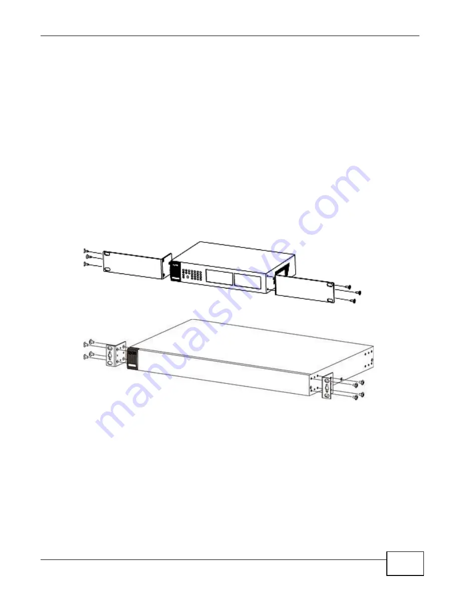
Attaching the Mounting Brackets to the Switch

1

Position a m ounting bracket  on one side of the Switch, lining up the four screw holes on the bracket 
with the screw holes on the side of the Switch.   

Figure 12   

At t aching t he Mount ing Bracket s ( GS1100- 16)

Figure 13   

At t aching t he Mount ing Bracket s ( GS1100- 24)

2

Using a # 2 Philips screwdriver, install the M3 flat head screws through the m ounting bracket holes 
into the Switch.

3

Repeat steps 

1

 and 

2

 to install the second m ounting bracket on the other side of the Switch.

4

You m ay now m ount the Switch on a rack. Proceed to the next section.

2.3.3  Mounting the Switch on a Rack

1

Position a m ounting bracket ( that is already attached to the Switch)  on one side of the rack, lining 
up the two screw holes on the bracket with the screw holes on the side of the rack. 

Содержание GS1100 Series

Страница 1: ...Quick Start Guide www zyxel com GS1 1 0 0 Series Unmanaged Gigabit Ethernet Switch Version 1 00 Edition 3 06 2012 Copyright 2012 ZyXEL Communications Corporation User s Guide...

Страница 2: ...THIS GUIDE FOR FUTURE REFERENCE Screenshots and graphics in this book may differ slightly from your product due to differences in your product firmware or your computer operating system Every effort h...

Страница 3: ...on and Connection 9 2 1 Rear Panel 9 2 1 1 Rear Panel Power Connection 9 2 2 Front Panel 9 2 2 1 RJ 45 Auto negotiating Ports 10 2 2 2 IEEE 802 3az EEE 10 2 2 3 Mini GBIC Slots GS1100 24 Only 10 2 2 4...

Страница 4: ...Table of Contents GS1100 Series User s Guide 4...

Страница 5: ...businesses The GS1100 8HP has four GbE PoE ports that can supply power to the connected PoE powered devices The GS1100 24 has two mini GBIC ports for uplink connection Use mini GBIC transceivers in th...

Страница 6: ...bps and duplex mode Half Full auto detection Supports store and forward switching Supports automatic address learning Supports IEEE 802 3az EEE Support IEEE 802 3af and IEEE 802 3at PoE standards only...

Страница 7: ...t networks to connect to the corporate backbone or for connecting network segments The following figure depicts a typical segment bridge application of the Switch in an enterprise environment The two...

Страница 8: ...e 8 In the figure below the IP camera and IP phone get their power directly from the Switch Aside from minimizing the need for cables and wires PoE removes the hassle of trying to find a nearby electr...

Страница 9: ...end of the supplied power cord to the power receptacle on the back of the Switch and the other end to the appropriate power source For the GS1100 8HP and GS1100 16 use the POW ER ON OFF switch to have...

Страница 10: ...e is enabled by default on the GS1100 16 and GS1100 24 Press in the I EEE 8 0 2 3 az EEE ON OFF button on the GS1100 8HP front panel to turn on the EEE feature Disable it if the remote side doesn t su...

Страница 11: ...les to the transceiver Figure 6 Transceiver Installation Example Figure 7 Connecting the Fiber Optic Cables 2 2 3 2 Transceiver Removal Use the following steps to remove a mini GBIC transceiver SFP mo...

Страница 12: ...for the different connection speeds You can use either crossover or straight through cables for all the ports 2 2 5 Front Panel LEDs The LED Indicators give real time information about the status of t...

Страница 13: ...urn on the Switch Table 3 The Front Panel LED Descriptions LED COLOR STATUS DESCRIPTION PWR Green On The Switch is on and receiving power Off The Switch is not receiving power PoE MAX Red On Power sup...

Страница 14: ...n down the back of the Switch Note Make sure the screws are securely fixed to the wall and strong enough to hold the weight of the Switch with the connection cables 2 Align the holes on the back of th...

Страница 15: ...Mounting Brackets to the Switch 1 Position a mounting bracket on one side of the Switch lining up the four screw holes on the bracket with the screw holes on the side of the Switch Figure 12 Attachin...

Страница 16: ...ting the Switch on a Rack GS1100 16 Figure 15 Mounting the Switch on a Rack GS1100 24 2 Using a 2 Philips screwdriver install the M5 flat head screws through the mounting bracket holes into the rack 3...

Страница 17: ...or for assistance The LI NK ACT LED does not light up when a device is connected Verify that the attached device s is turned on and properly connected to your Switch Make sure the network adapters are...

Страница 18: ...ems that affect your network performance Refer to Section 2 2 4 on page 12 for more information on network cable types Cabling Length If you use longer cables than are needed transmission quality may...

Страница 19: ...l area is likely to cause harmful interference in which case the user will be required to correct the interference at his own expense CE Mark Warning This is a class A product In a domestic environmen...

Страница 20: ...r unit Opening or removing covers can expose you to dangerous high voltage points or other risks ONLY qualified service personnel should service or disassemble this device Please contact your vendor f...

Страница 21: ...9 E EEE 5 10 Energy Efficient Ethernet 10 F Faulty cables 18 FCC interference statement 19 Front Panel 9 Front Panel Connections 12 H High Power over Ethernet 7 I IEEE 802 3at 7 IEEE 802 3az 10 instal...

Страница 22: ...R rack mounting 14 Rear Panel 9 Rear Panel Power Connection 9 registration product 20 S safety warnings 20 Small Form factor Pluggable SFP 10 Standalone Workgroup 6 T transceiver MultiSource Agreement...

Отзывы: