


Chapter 2 Hardware Description and Connection
GS1100 Series User’s Guide
14
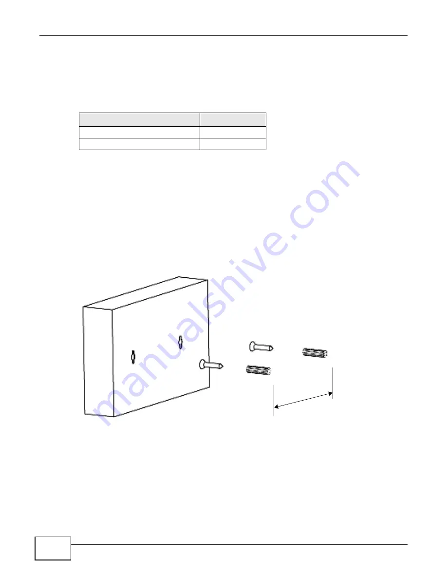
2.3.1 Wall Mounting
Do the following to attach your Switch to a wall.
See
Table 5 on page 14
for how far apart to place the screws.
1
Screw the two screws provided with your Switch into the wall ( see the figure in step 2) . Use screws
with 6 m m ~ 8 m m ( 0.24" ~ 0.31") wide heads. Do not screw the screws all the way in to the wall;
leave a sm all gap between the head of the screw and the wall.
The gap m ust be big enough for the screw heads to slide into the screw slots and the connection
cables t o run down t he back of t he Swit ch.
Note: Make sure t he screws are securely fixed t o t he wall and st rong enough t o hold t he
weight of t he Swit ch with t he connect ion cables.
2
Align t he holes on t he back of t he Sw it ch wit h t he screw s on t he wall. Hang t he Swit ch on t he
screws.
The Switch should be wall-mounted horizontally. The Switch's side
panels with ventilation slots should not be facing up or down as this
position is less safe.
2.3.2 Rack Mounting
The Switch can be m ounted on an EI A standard size, 19- inch rack or in a wiring closet with other
equipm ent. Follow t he steps below to m ount your Switch on a standard EI A rack using a rack-
m ount ing kit .
Table 5
Distance between the centers of the holes for wall mounting
MODEL
DISTANCE
GS1100- 8HP
120 m m
GS1100- 16
150 m m