ZOOM G9.2tt
52
Other Functions
Using the ARRM function
The G9.2tt incorporates an innovative feature
c a l l e d A R R M ( A u t o - R e p e a t R e a l - t i m e
Modulation) which uses various internally
generated control waveforms to cyclically modify
effect parameters. You can select for example a
triangular waveform and apply it to the wah
frequency as a control target. The resulting effect
is shown below.
This section explains the use of the ARRM
feature.
1.
In play mode, select the patch.
HINT
The ARRM settings can be made separately for
each patch.
2.
Press the [TOTAL/FUNCTION] effect
module key to switch to edit mode,
and then turn the [TYPE] knob to
bring up the indication “ARRM” on
the display.
3.
Turn parameter knob 1 to select the
control target parameter.
A s y o u t u r n p a r a m e t e r k n o b 1 , t h e e f f e c t
parameter, effect type, and effect module change.
HINT
• The parameters that can be selected as control
targets are the same as can be selected for
operation by the expression pedal. See the
section “Effect Types and Parameters” on page
60 – 75.
• When “NOT Assign” is displayed, no parameter
is assigned as control target and the ARRM
function is disabled.
4.
To set the adjustment range for the
parameter to be controlled, use
parameter knob 2 (minimum value)
and parameter knob 3 (maximum
value).
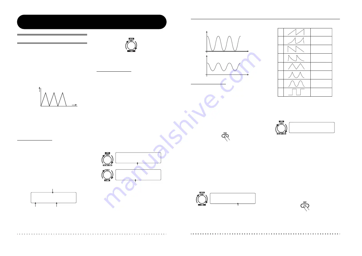
The settings selected with parameter knobs 2 and
3 determine the value when the control waveform
reaches minimum value and maximum value.
The difference between a parameter setting range
of 0 (minimum) – 100 (maximum) and 20
(minimum) – 80 (maximum) is evident from the
graph on the next page.
Wah Wah
Wah
Wow Wow Wow
Wah
Frequency
Time
Control target parameter name
Module name
Effect type name
MOD:Chorus
MOD:Chorus
¡ARRM=Mix
ARRM=Mix
Minimum value
Maximum value
£MAX=100
MAX=100
TOTAL:ARRM MAX
TOTAL:ARRM MAX
™min= 0
min= 0
TOTAL:ARRM min
TOTAL:ARRM min
Other Functions
ZOOM G9.2tt
53
HINT
• The available range setting depends on the
parameter.
• It is also possible to set “min” to a higher value
than “MAX”. In that case, the control change
direction will be reversed.
5.
To select the control waveform type
and cycle, press the [PAGE] key once
to switch the page.
T h e A R R M f u n c t i o n h a s a t o t a l o f f i v e
parameters. To set parameters 4 and 5, press the
[PAGE] key first and then use parameter knobs 1
and 2. (To return to adjusting parameters 1 - 3,
press the [PAGE] key once more.)
6.
Turn parameter knob 1 to select the
control waveform.
The display changes as follows.
Available waveforms are shown at right.
7.
Turn parameter knob 2 to select the
control waveform cycle.
The display changes as follows.
The control waveform cycle uses the patch
specific tempo (
→
p. 39) as reference and is
displayed as eighth note, quarter note, or quarter
note x numeral (see table on page 40).
The numeral after x (2 – 20) indicates the duration
of a cycle in multiple quarter notes. When “2” is
selected, the control waveform changes in a cycle
interval that corresponds to half a note of the
patch specific tempo. When “4” is selected, the
cycle is 4 beats (1 measure of a 4/4 beat).
8.
When the ARRM setting is complete,
press the [EXIT] key.
The unit returns to play mode. Store the patch as
necessary.
Parameter value
Parameter value
MAX=100
min=0
100
0
MAX=80
min=20
80
20
Time
Time
Control waveform type
¢Type=Triangle
Type=Triangle
TOTAL:ARRM WAVE
TOTAL:ARRM WAVE
Rising sawtooth
(Up Saw)
Rising fin
(Up Curve)
Falling sawtooth
(Down Saw)
Falling fin
(Down Curve)
Triangle
(Triangle)
Square triangle
(Square Tri)
Sine wave
(Sine)
Square wave
(Square)
2
1
3
4
6
5
7
8
ßSync=
Sync=∑x2
x2
TOTAL:ARRM SYNC
TOTAL:ARRM SYNC


