background image

page 10

enGlisH


Legacy™ Model LRZM Pool/Spa Heater   

|

   Installation and Operation Manual

At least 457 mm access must be available in 

front of the heater for burner removal and access to the 

igniter. 

If the heater is to be installed in a garage, or  

similar structure, all burners and burner ignition 

devices must have a minimum 457 mm clearance 

above the floor. 

This heater must be installed at least 1.52 m from 

the inside wall of a pool unless the heater is separated 

from the pool by a solid fence, wall or other permanent 

solid barrier.

2.5.3  Flooring

The heater must be installed on a 

level 

surface 

of noncombustible construction or on fire-resistant 

slabs or arches. Noncombustible flooring is defined 

as flooring material and surface finish not capable of 

being ignited and burning and with no combustible 

materials against the underside. Acceptable materials 

are those consisting entirely of a combination of steel, 

iron, brick, tile, concrete, slate, glass or plaster.

 Do not 

install the heater directly on a combustible wood or 

carpet floor without placing a noncombustible platform 

between the floor and the heater. 

The heater can be installed on a combustible floor 

if a noncombustible base assembly, available from 

Zodiac, is used. See the heater rating plate or the Parts 

List (Section 12) of this manual for the appropriate 

base part number. 

Heaters must never be installed 

directly on carpeting. 

As an alternative to the Zodiac noncombustible 

base plate, the heater may be placed on a combustible 

surface when there is a platform under the heater made 

of hollow masonry no less than 102 mm thick, covered 

with sheet metal at least 24 gauge thick and extend-

ing beyond the full width and depth of the heater by at 

least 153 mm in all directions. The masonry must be 

laid with ends unsealed, and joints matched to provide 

free circulation of air from side to side through the 

masonry (see Figure 2). If the heater is installed in a 

carpeted alcove, the entire floor of the alcove must be 

covered by a noncombustible panel.

2.5.4  outdoor installation

The Legacy Model LRZ millivolt heater can be 

installed in the low-profile Type A flueless configu

-

ration as received from the factory. Alternately, the 

heater may be installed outdoors using a Type B11 

vent cap. This vent cap is used in high wind installa-

tions. No draft hood is required for this type of outdoor 

installation.

Locate the heater in an 

open, unroofed area

. Do 

not install the heater under a deck. Do not locate the 

heater below or adjacent to any doors, glass openings, 

louvers, grills, etc., which connect in any way with an 

inhabited area of a building, even though the access 

might be through another structure (e.g., a garage 

or utility room). There must be a minimum of 2 m 

horizontally or 2 m vertically between the heater and 

any door, glass opening, or gravity inlet into a build-

ing. See Figure 3.

The top surface of the heater must be at least  

0.91 m above any forced air inlet, or intake ducts 

located within 3.0 m horizontally.

If the heater is installed under an overhang, there 

must be a minimum clearance of 1.5 m above the top 

of the heater and the structure should not overhang the 

heater more than 0.30 m. The area under the overhang 

must be open on three (3) sides. This prevents combus-

tion gases from being diverted into living areas 

through doors, windows, or gravity inlets.

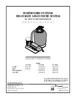
Figure 2.  noncombustible platform

153mm

153mm

notes:

1.  Blocks must provide a solid base and be braced so they 

cannot slip out of place.

2.  Air openings in blocks must be arranged to provide un-

restricted opening through entire width or length of base.

3.  Sheet metal must be at least 24 ga. and extend 153 mm 

beyond the heater jacket on all sides.

Sheet Metal Min. 

Thickness 24 Ga

Hollow Concrete 

Block Platform 

table 3.   Minimum Heater Clearances  

From Combustible surfaces

Note: Clearances listed in Table 4 are manufacturer's tested 

values. These are given as minimum values. Where local 

codes apply, and values are different than those listed in 

Table 4, use the greater value to ensure safe operation. 

SIDE OF HEATER

MINIMUM CLEARANCE

Millimeters

BLANK

203

REAR 

150

PIPING

355

TOP

1120

FRONT

457

Содержание Legacy LRZ

Страница 1: ...wed exactly a fire or explosion may result causing property damage personal injury or death H0316500 Rev F WARNING The GAS SAFETY INSTALLATION AND USE REGULATIONS 1998 as amended place statutory requi...

Страница 2: ......

Страница 3: ...3 3 Inspection and Replacement of Existing Vent System with New Components 13 Section 4 Gas Connections 13 4 1 Gas Supply and Piping 13 4 2 Burner Pressure 14 4 3 Special Precautions for LPG 14 Secti...

Страница 4: ...11 4 1 Gas Valve 31 11 4 2 Pilot Generator 33 11 4 3 Fusible Link 33 11 4 4 Fireman Switch and External Interlocks 33 11 4 5 Limit Switches 34 11 4 6 Water Pressure Switch 34 11 4 7 Temperature Contro...

Страница 5: ...symbol Be sure to read and comply with all of the warnings and cautions 1 2 1 Spa Hot Tub Safety Rules WARNING Elevated water temperature can be hazardous Consult heater operation and installation ins...

Страница 6: ...warranty does NOT cover damage caused by improper assembly installation operation or field modification Also damage to the heat exchanger by corrosive water is NOT covered by the warranty See Section...

Страница 7: ...areas Install the Legacy Model LRZ millivolt heater vent caps and draft hoods in accordance with the procedures in this manual local codes and ordinances and in accordance with the latest edition of t...

Страница 8: ...riate ventilation directly to the outside WARNING The Legacy heater is certified to European require ments for use only as a swimming pool or spa heater The Legacy heater must not be used for any othe...

Страница 9: ...onsible for such water loss or flooding or result ing damage The Legacy Model LRZ millivolt heater may be installed indoors or outdoors as outlined in later sections Location of the heater below or ab...

Страница 10: ...f the alcove must be covered by a noncombustible panel 2 5 4 Outdoor Installation The Legacy Model LRZ millivolt heater can be installed in the low profile Type A flueless configu ration as received f...

Страница 11: ...n excess of 60 kW total rated input Exhaust Fans or Vents Any equipment which exhausts air from the room where the heater is installed can deplete the combustion air supply or reverse the natural draf...

Страница 12: ...either case the result can be release of combustion products to the indoors This can cause serious injury or death by carbon monoxide poison ing or asphyxiation All indoor installations and outdoor sh...

Страница 13: ...t least five 5 feet in vertical height above the draft hood outlet Double wall or equivalent vent pipe is recom mended IMPORTANT NOTE Do not use sheet metal screws at the snap lock joints of gas vents...

Страница 14: ...about specific installation restrictions in your area Section 5 Water Connections 5 1 Water Piping Figure 6 illustrates typical piping for pool equip ment in pool spa combination pools For normal inst...

Страница 15: ...ions have been written to include the steps needed when reversing the water connections on an existing installation If you are reversing the headers on a new installation some steps will be ignored Wh...

Страница 16: ...remove the coupling nuts from the header and disconnect the water supply from the heater 9 Remove the 10 bolts and washers from the inlet outlet header and remove the header from the tube assembly 10...

Страница 17: ...G COUPLING NUT PVC OR CPVC PIPE 21 Use plastic wire ties to refasten the temperature sensor high limit switch and water pressure switch wires to each other Bundle the wires near the control panel and...

Страница 18: ...by reaming it with a 9 5 mm 3 8 inch drill bit 4 Open the hole again by reaming it with a 12 7 mm 1 2 inch drill bit CAUTION Initially drilling a 12 7 mm 1 2 inch hole without reaming may cause the bi...

Страница 19: ...cal require ments exists In the event no such state or local requirement exists the installer or maintainer must be a professional with sufficient experience in pool equipment installation and mainten...

Страница 20: ...any residual heat contained in the heat exchanger back to the pool To install a time clock auxiliary switch into the heater wires see Figure 16 1 Remove heater door 2 Remove the factory installed wir...

Страница 21: ...to manual ON OFF operations of any controls fitted in the gas control circuit 12 Check the operation of the flame failure safety device using the following steps a Extinguish the main burner and pilot...

Страница 22: ...d shutdown instructions can also be found attached to the wall inside the control compartment door See Figure 18 1 Remove the service door on the front of the heater the temperature control setting an...

Страница 23: ...intained between 7 4 and 7 6 when operating unit see section entitled Water Chemistry in operating manual 3 BACKWAshing Turn heater off 20 minutes before backwashing or shutting down filter to prevent...

Страница 24: ...rn the gas control knob clockwise until it stops at the OFF position see Figure 19 3 Wait five 5 minutes before lighting the pilot 4 Turn the knob on the gas valve counterclockwise to PILOT then push...

Страница 25: ...aking place possibly due to a low pH value combined with other chemistry problems The condi tion can be corrected by changing the spa water and closely monitoring the pH factor and chemical proper tie...

Страница 26: ...njury or death 9 3 1 Owner Inspection Zodiac recommends that you inspect the heater on a continual basis and especially after abnormal weather conditions The following basic guidelines are suggested f...

Страница 27: ...temperature limit 8 Perform a temperature rise test in accordance with Section 11 6 9 If the heater is equipped with a pressure relief valve check for corrosion in and around the valve With the filter...

Страница 28: ...ubleshooting Table 8 lists some of the more common problems causes and solutions encountered when running the heater Most problems occur when the heater is being started for the first time after insta...

Страница 29: ...gas supply B Low burner gas pressure C Heater size inadequate D Low temperature rise A Gas meter too small Gas line from meter to heater too small B Gas pressure on heater burner should be adjusted to...

Страница 30: ...ws into the burner a negative pressure is created at the opening of the burner This negative pressure pulls air into the burner with the gas and mixes the two together As the gas air mixture flow thro...

Страница 31: ...lot generator and control circuits and where to take measurements Location numbers and letters in circles have been added and will be referenced in the follow ing sections As stated at the beginning o...

Страница 32: ...16 11 12 13 14 1 4 5 2 3 17 TEMPERATURE CONTROL ROLL OUT SWITCH FUSIBLE LINK FIREMAN SWITCH PRESSURE SWITCH HIGH LIMIT GAS VALVE TH TP PILOT GENERATOR PILOT IGNITER BK W W R BK BLACK R RED W WHITE H0...

Страница 33: ...st point 4 the roll out switch fusible link has failed This indicates higher than normal temperatures in the component compartment vestibule Normal component compart ment temperature is well below 148...

Страница 34: ...o voltage here means that the limit switch is open and must be replaced If voltage is detected at test point 12 move the black lead of the meter to the terminal of the water pressure switch where the...

Страница 35: ...clean before making any pressure switch adjustment A dirty filter will restrict the water flow and the pressure switch cannot be adjusted properly To adjust the pressure switch refer to Figure 26 and...

Страница 36: ...the header see Figure 22 Loosen the nut so that the screw can be adjusted A slight water leak past the nut may be expected Turn the screw counterclockwise to decrease the tempera ture rise and clockwi...

Страница 37: ...hield Partition 125 400 R0478201 05 41 Flue Collector Assembly 125 400 R0470501 05 42 Outdoor Vent Cap 125 175 R0491606 42 Outdoor Vent Cap 250 400 R0491603 05 43 Indoor Draft Hood 125 175 R0499606 43...

Страница 38: ...Legacy Model LRZM Pool Spa Heater Installation and Operation Manual 12 3 General Exploded View 28 61 48 66 72 71 70 49 77 64 65 76 74 10 34 35 61 51 70 75 79 27 46 47 5 42 43 44 39 40 38 41 62 63 68 6...

Страница 39: ...NGLISH Installation and Operation Manual Legacy Model LRZM Pool Spa Heater 12 4 Detailed Exploded View 37 29 48 52 60 52 55 54 32 31 33 53 57 59 7 57 52 14 14 12 13 9 8 11 21 23 25 21 36 5 19 15 18 24...

Страница 40: ...81 1 800 822 7933 www ZodiacPoolSystems com ZODIAC is a registered trademark of Zodiac International S A S U used under license All trademarks referenced herein are the property of their respective ow...

Отзывы: