background image

Page 19

ENGLISH


Installation and Operation Manual   

|

   Jandy® Legacy™ Model LRZM Pool/Spa Heater by Zodiac®

20.  Reinstall the temperature sensor in the inlet/

outlet header and tighten the nut.

21.  Reconnect the black and white wires to the water 

pressure switch.

22.  Use plastic wire ties to refasten the temperature 

sensor, high limit switch and water pressure 

switch wires to each other. Bundle the wires near 

the control panel and fasten them with a wire tie. 

 cautioN

In order to prevent property damage or injury, be 

sure that none of the wires are in contact with a 

sharp edge or a hot surface.


atteNtioN

Afin d'empêcher des dégâts matériels ou des bles-

sures, assurez-vous qu'aucun des fils n'est en con-

tact avec un bord tranchant ou une surface chaude.

23.  Install the return header side cover plate on the 

right side of the unit.

24.  Install the I/O header side cover plates, top and 

bottom on the left side of the unit.

25.  Replace the front panel (door).

5.5 

connections at Heater

The Legacy heater has a standard two (2) inch 

water header and coupling design. With this feature, 

only nominal two inch PVC or CPVC may be connect-

ed to the heater. However, by installing the appropriate 

pipe adapters and two short pieces of two inch plastic 

pipe (supplied by the installer), any size existing pipe 

may be fitted to the heater.

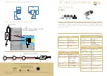
To connect a section of 2” PVC or CPVC pipe 

to the heater, first slip a coupling nut onto the pipe. 

Then prepare the end of the pipe with the proper PVC/

CPVC primer and glue. 

Follow the manufacturer’s instructions provided 

with the primer and glue for preparation procedures 

and curing times. Apply the slip-fit side of the coupling 

to the end of the pipe. Allow the glue to cure complete-

ly. Set the o-ring into the groove on the face of the 

coupling. Slide the coupling nut up to the coupling and 

tighten it to the threaded connection on the header. See 

Figure 12.

5.6 

Pressure Relief valve

A pressure relief valve (PRV) is recommended in 

all installations, and is mandatory in any installation 

in which the water flow can be shut off between the 

heater outlet and the pool/spa.

A pressure relief valve is not supplied with the 

Legacy heater. However, it is recommended that a 

pressure relief valve be installed and may even be 

required by local codes. Be sure to check any appli-

cable installation codes in your area to determine 

whether a pressure relief valve is required. See Section 

11.2, Parts List of this manual for the appropriate kit 

part number.

The maximum working pressure of this heater 

is 75 psi. Be sure to take into consideration the 

maximum allowable pressure of the other components 

in the system when selecting a PRV. Any pressure 

relief valve installed must comply with provisions of 

the standard described in ANSI Z21.22 for the United 

States or CSA 4.4 in Canada.  

Follow these steps to install a pressure relief valve:  

1.  To protect the threads while drilling, screw the 

brass adapter (included with the Jandy PRV kit) 

into the blind threaded hole on the top of the 

inlet/outlet header.

2.  Using the countersink in the center of the blind 

hole as a guide, drill a 1/4 inch hole through the 

plastic. See Figure 13.

3.  Open the hole by reaming it with a 3/8 inch drill 

bit.

4.  Open the hole again by reaming it with a 1/2 inch 

drill bit.

 cautioN

Initially drilling a 1/2" hole without reaming may 

cause the bit to "grab" on the plastic. This may 

cause personal injury or damage the plastic header.


atteNtioN

Si vous commencez à percer le trou de ½" sans 

alésage préalable, la mèche risque de « mordre » 

dans le plastique. Vous risquez de vous blesser ou 

d’endommager le tuyau collecteur de plastique.

5.  Remove the brass adapter and clean the cuttings 

out of the hole.

6.  Install the rubber washer at the bottom of the 

hole. See Figure 14.

7.  Thread the adapter into the hole and tighten so 

Figure 12. Piping to Heater

O-RING

TAILPIECE

UNION NUT

PVC OR CPVC PIPE

Содержание Jandy Legacy LRZ Millivolt

Страница 1: ...er installation and or operation can create carbon monoxide gas and flue gases which can cause serious injury property damage or death For indoor installations as an additional measure of safety Zodia...

Страница 2: ......

Страница 3: ...17 5 4 Reversible Water Connections 17 5 5 Connections at Heater 19 5 6 Pressure Relief Valve 19 5 7 Auxiliary Components Chlorinators Ozone Generators and Sanitizing Chemicals 20 Section 6 Electrica...

Страница 4: ...LRZM Pool Spa Heater by Zodiac Installation and Operation Manual Section 11 Replacement Parts 38 11 1 Ordering Information 38 11 2 Parts List 39 11 3 General Exploded View 41 11 4 Detailed Exploded Vi...

Страница 5: ...erved when using the spa AVERTISSEMENT Les R glements suivants pour Cuves Thermales tel que recommand s par la Commission U S de S curit des Produits pour les Consommateurs devraient tre respect s lor...

Страница 6: ...oad on filter systems 1 3 Warranty The Legacy heater is sold with a limited factory warranty Details are specified on the back cover of this manual Make all warranty claims to a Jandy dealer or direct...

Страница 7: ...CPVC pipe nipples to PVC pool plumbing 3 A noncombustible platform for installation on combustible surfaces see Section 2 3 3 Noncombustible bases are available from your Jandy distributor 4 A factor...

Страница 8: ...is manual local codes and ordinances and in accordance with the latest edition of the appropriate national code See Section 1 4 Codes and Standards All gas fired products require correct installation...

Страница 9: ...on all sides for maintenance and inspection There must also be minimum distances maintained from combustible surfaces See Table 2 At least 18 inches 457mm access must be avail able in front of the hea...

Страница 10: ...y a noncombustible panel 2 3 4 Outdoor Installation Legacy heaters can be installed in the low profile top configuration as received from the factory or with an optional high wind vent cap Locate the...

Страница 11: ...e downdraft conditions exist locate the heater at least three 3 feet 0 91 m from vertical surfaces e g nearby buildings and walls The addition of a vent cap may be necessary In Florida it is required...

Страница 12: ...B149 1 For combustion air supply openings however the requirements of Table 3 MUST be followed for safe and proper operation The minimum combustion air openings allowed in CAN CSA B149 1 are NOT suffi...

Страница 13: ...vent pipe and 90 elbows reductions and restrictions Horizontal runs must have at least a 1 4 inch rise per foot 20mm per meter in the direction of flow These requirements are summarized in Table 3 Not...

Страница 14: ...lled to replace an existing pool heater it is recommended that a new appropriate venting system be installed with the new heater However if an existing venting system must be used be sure to carefully...

Страница 15: ...with water after testing ATTENTION Certaines solutions d essai d tanch it y compris l eau et le savon peuvent causer de la corrosion ou de la fissuration Rincez les tuyaux l eau apr s l essai d tanch...

Страница 16: ...f provision for proper ventilation is not made Installation of pool heaters in enclosed areas such as pits is not recom mended Consult the National Fuel Gas Code NFPA 54 ANSI Z223 1 latest edition the...

Страница 17: ...nd adjust the flow using the bypass valve until the proper temperature rise is obtained 5 4 Reversible Water Connections NOTE Reversing the header requires a longer syphon tube order part number R0483...

Страница 18: ...the I O header side cover plates top and bottom See Figure 10 4 Remove the return header side cover plates top and bottom See Figure 10 5 Tag and disconnect the white wire on the pressure switch PS a...

Страница 19: ...aded connection on the header See Figure 12 5 6 Pressure Relief Valve A pressure relief valve PRV is recommended in all installations and is mandatory in any installation in which the water flow can b...

Страница 20: ...g may crack the header atteNtioN Afin d emp cher des d g ts mat riels ne serrez pas trop Le serrage excessif peut provoquer des fissures dans la t te DO NOT TIGHTEN WITH A WRENCH Overtightening may cr...

Страница 21: ...s all electrical equipment in the system and on the equip ment pad Bonding lugs must be connected with a solid copper wire not smaller than 8 AWG 6 AWG in Canada Failure to do so will void warranty Ad...

Страница 22: ...fin de course max 130 Pressure Switch Manostat Pilot Gen G n rateur de veilleuse Pilot Veilleuse Piezo Sparker tinceleur pi zo lectrique Fusible Link Maillon Fusible Fireman Switch Connection Montage...

Страница 23: ...is operation before starting the heater Start the heater in accor dance with the Operating Instructions section of this manual with particular attention to the lighting and shutdown instructions and t...

Страница 24: ...t to your preferences follow the instructions outlined on the following page as shown in Figure 18 Read and follow all safety instructions first A more detailed set of instructions of the opera tion o...

Страница 25: ...s tapes 3 et 4 5 Faire tourner le bouton du robinet gaz vers la gauche jusqu la position ON 6 Apr s avoir remis en place le panneau d acc s r gler le thermostat sur la valeur voulue et mettre l interr...

Страница 26: ...to close at too low of a flow can damage the appliance Adjust the switch to turn the heater off not on ATTENTION Le manocontact de pression d eau doit tre r gl de fa on ce que l appareil cesse de fonc...

Страница 27: ...With the plug removed install the special thread adapter and Pete s Plug fitting and insert a pocket thermometer A temperature rise measurement kit is available through your Jandy distributor See Sect...

Страница 28: ...of the water Be sure to keep your chemical levels within the values indicated in Table 7 Zodiac Pool Systems Inc does not warrant heat exchangers damaged by corrosive chemical levels or excess dissol...

Страница 29: ...especially at spring start up are impor tant to keep your heater running safely and efficiently through the years Improper maintenance can result in conditions where nausea or asphyxiation from carbon...

Страница 30: ...ez pas cet appareil s il a t plong dans l eau m me partiellement Faites inspecter l appareil par un technicien qualifi et remplacez toute partie du syst me de contr le et toute com mande qui ont t plo...

Страница 31: ...che tenez votre t te et votre visage loin du br leur pour viter tout risque de blessure NOTE Keep this manual in a safe place for future reference by you and your professional technician when inspecti...

Страница 32: ...old gas pressure C Heater size inadequate D Low temperature rise A Gas meter too small Gas line from meter to heater too small B Gas pressure on heater manifold should be adjusted to 4 0 W C natural g...

Страница 33: ...ts in the pool system including pump filters and strainers water valves gas supply and time clocks have an effect on heater operation Confirm that the Legacy heater control switch is set to ON and tha...

Страница 34: ...l temperature in the vent system It is mounted to the flue collector assem bly Excessive temperatures will cause the switch to open Excessive temperatures can be caused by inadequate water flow or a d...

Страница 35: ...n rateur de veilleuse Pilot Veilleuse Piezo Sparker tinceleur pi zo lectrique Fusible Link Maillon Fusible Fireman Switch Connection Montage contacteur pompier 150 High Limit Switch Contacteur de fin...

Страница 36: ...point 1 Touch the black lead of the meter to the terminal of the fusible link where the white wire from the gas valve is connected test point 3 If no voltage is detected at test point 3 the wire betw...

Страница 37: ...e meter to the other terminal of the 130 F 55 C limit switch test point 10 Low or no voltage here means that the limit is open and must be replaced If voltage is detected at test point 10 move the bla...

Страница 38: ...he inlet of the filter system Find the temperature in the chart that is closest to your temperature reading of the pool water Compare your ohmmeter reading to the resistance number in the chart Rememb...

Страница 39: ...gh Limit Switch Assembly All R0457401 39 High Limit Set 130 F 150 F All R0457200 40 High Limit Switch 130 F All R0457300 41 High Limit Switch 150 F All R0023000 Key No Description Model No Order Part...

Страница 40: ...483401 05 98 Heat Deflector Guard Rear 125 400 R0483501 05 99 Controller Mounting Panel 125 400 R0483901 05 100 Weather Stripping All R0491000 101 Grommet 7 8 All R0492800 Optional Components 102 Nonc...

Страница 41: ...tion and Operation Manual Jandy Legacy Model LRZM Pool Spa Heater by Zodiac 11 3 General Exploded View 49 50 51 46 47 45 48 88 94 93 92 56 35 97 83 90 91 101 89 98 96 16 83 11 99 84 85 86 55 58 42 43...

Страница 42: ...dy Legacy Model LRZM Pool Spa Heater by Zodiac Installation and Operation Manual 11 4 Detailed Exploded View 59 63 41 40 62 61 25 33 60 27 79 80 77 59 18 17 13 15 44 9 22 28 31 29 23 24 38 8 3 4 6 1 2...

Страница 43: ...Page 43 ENGLISH Installation and Operation Manual Jandy Legacy Model LRZM Pool Spa Heater by Zodiac 73 74 70 71 76 38 41 40 25 69 68 76 77 79 80 77 67 72 35 75 67 66 65 64 82 55...

Страница 44: ...al S A S U used under license All trademarks referenced herein are the property of their respective owners 2012 Zodiac Pool Systems Inc H0299600 Rev G 1202 Zodiac Pool Systems Inc 2620 Commerce Way Vi...

Отзывы: