ZLIM42C Integrated Open Loop Step Motor Manual Version 1.03
ZLIM42C Integrated Open Loop Step Motor Manual Version 1.03
9
Shenzhen ZhongLing Technology Co.,Ltd. TEL: +86-0755-29799302 FAX
:
+86-0755-2912 4283 WEB:
Shenzhen ZhongLing Technology Co.,Ltd. TEL: +86-0755-29799302 FAX
:
+86-0755-2912 4283 WEB:
3.
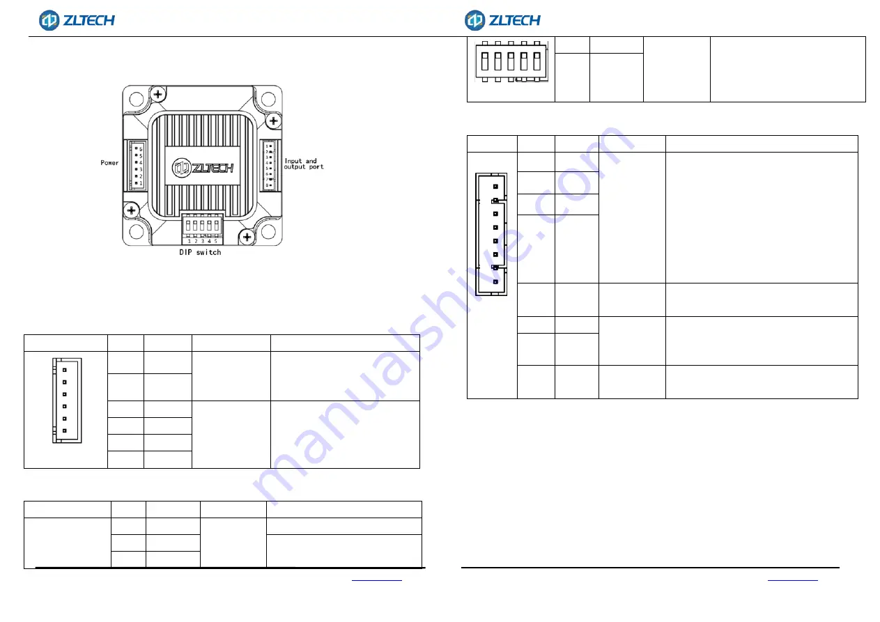
DRIVER INTERFACE AND WIRING
3.1.
Interface Definition
3.1.1 Power input port
Port
Pin
Mark
Name
Function
6
5
4
3
2
1
6
DC
Power interface
Power supply 20V-48V
5
GND
4
CANH
Communication
interface
CAN communication interface
3
CANL
2
CANH
1
CANL
3.1.2 DIP switch
Port
Pin
Mark
Name
Function
1
SW1
DIP switch
CAN terminal resistance selection
2
SW2
Driver address setting
3
SW3
1 2 3 4 5
4
SW4
5
SW5
3.1.3 Control signal port
Port
Pin
Mark
Name
Function
1
2
3
4
5
6
7
8
1
X0
Single-ended
input
The default input voltage is 5V.
For other
voltages, current limiting resistors must
be added
, for example: 12V, external 1K 1
/ 2W resistor; 24V, external 2K 1 / 2W
resistor.
Supports both of NPN and PNP wiring
modes, port functions can be modified by
software.
2
X1
3
X2
4
X3
5
XCOM
Common
input
6
Y0
Single-ended
output
Supports both of NPN and PNP wiring
modes, port functions can be modified by
software.
7
Y1
8
YCOM
Common
output
3.2
Control Signal Wiring
ZLIM42C series driver provides 4 optically isolated programmable input interfaces,
which is compatible with NPN wiring and PNP wiring.
The 4(X0-X3) programmable input signals are isolated from the external control
interface by an optocoupler, and the driver is compatible with common cathode and
common anode connection methods, as shown in the figure below. In order to ensure
the reliable conduction of the optocoupler inside the driver, the driving current
provided by the controller is required to be at least 10mA.


