ZLIM42C Integrated Open Loop Step Motor Manual Version 1.03
ZLIM42C Integrated Open Loop Step Motor Manual Version 1.03
11
Shenzhen ZhongLing Technology Co.,Ltd. TEL: +86-0755-29799302 FAX
:
+86-0755-2912 4283 WEB:
Shenzhen ZhongLing Technology Co.,Ltd. TEL: +86-0755-29799302 FAX
:
+86-0755-2912 4283 WEB:
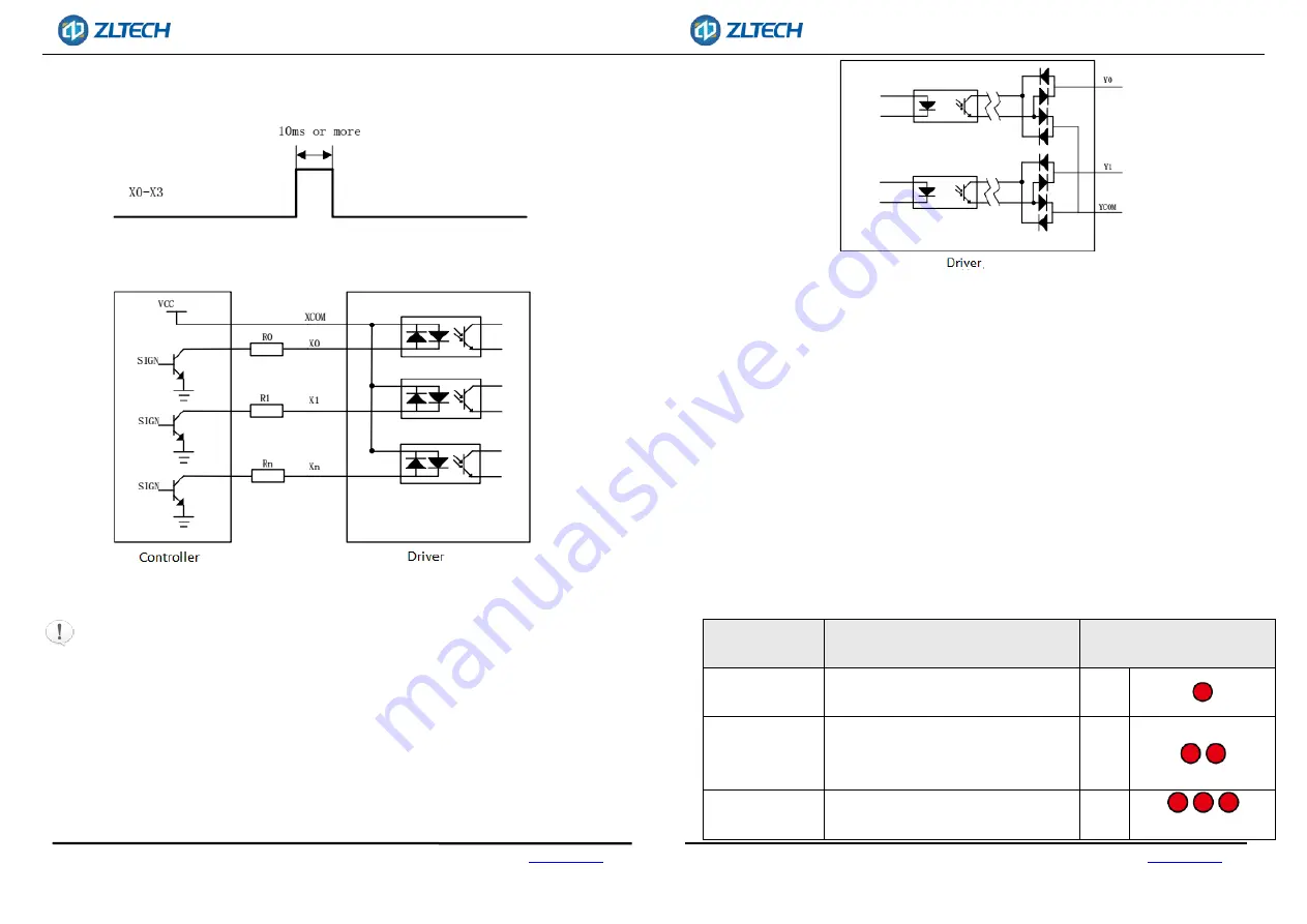
The level pulse width of X0-X input needs to be greater than 10ms, otherwise the driver
may not respond normally. X0-X3 timing diagram is shown in Figure 2.
Fig.2 Control signal interface wiring diagram
Fig.3 Input interface circuit
Note:
The default input voltage of the control signal is 5V. For other voltages,
current limiting resistors must be added, for example: 12V, external 1K 1 / 2W resistor;
24V, external 2K 1 / 2W resistor.
After the driver is powered on, X0-X3 defaults to the unspecified state. At this time, the
input signal is invalid. Users can configure X0-X3 input functions through the bus.
ZLIM42C series driver provides 2 optocoupler isolated output terminals, supports both
of NPN and PNP wiring modes, and can support high-level and low-level active
controllers.
3.3. CAN communication port description
ZLIM42C series driver provides 4PIN communication port. For pin definition, please
refer to 3.1.1 Power Port / Communication Port, which includes CANH, CANL, CANH and
CANL. Note: Please use shielded twisted-pair cables for communication cables and
ground them to ensure stable communication.
3.4. Status Indicator LED
The green LED is the power indicator, which is always on when the driver is powered up;
it is off when the driver is powered off. The red LED is the fault indicator. When the
driver fails, it will stop and prompt the corresponding fault code. The fault can be
cleared when the user powers off and restarts the power. The status indicator LED
represents different operation and fault information, as shown in the following table:
Status
Condition
Status indicator LED
description
over-voltage
Power supply voltage exceeds the
maximum rated voltage
1 red
over-current
The phase current through the motor
exceeds the rated current, or interphase
short circuit.
2 red
phase shortage
Poor contact between motor wire and
driver board.
3 red


