


Z8018x
Family MPU User Manual
86
UM005004-0918
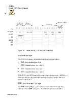
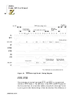
Figure 43. INT1, INT2 and Internal Interrupts Timing Diagram
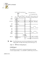
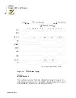
Dynamic RAM Refresh Control
The Z8X180 incorporates a dynamic RAM refresh control circuit
including 8-bit refresh address generation and programmable refresh
timing. This circuit generates asynchronous refresh cycles inserted at the
programmable interval independent of CPU program execution. For
systems which do not use dynamic RAM, the refresh function can be
disabled.
When the internal refresh controller determines that a refresh cycle should
occur, the current instruction is interrupted at the first breakpoint between
machine cycles. The refresh cycle is inserted by placing the refresh
address on A0–A7 and the RFSH output is driven Low.
T1
T1
T1
T1
T1
T1
T2
T2
T2
T2
T2
TW*
T3
T3
T3
T3
T3
T3
T2
TW*
Ti
PC Stacking
Vector Table Read
Op Code
fetch cycle
INT1, INT2, internal interrupt acknowledge cycle
Last MC
INT1,2
A0
–
A19
M1
MREQ
IORQ
RD
WR
PC
SP-1
SP-2
Vector
1
Starting
Address
Starting
Starting
* Two Wait States are automatically inserted.
D0
–
D7
ST
MC: Machine Cycle
PCL
PCH
Phi
address (L)
address (H)
Содержание Z8018 Series
Страница 1: ...www zilog com Z8018x Family MPU User Manual UM005004 0918...
Страница 206: ...Z8018x Family MPU User Manual 192 UM005004 0918...
Страница 220: ...Z8018x Family MPU User Manual 206 UM005004 0918...
Страница 250: ...Z8018x Family MPU User Manual 236 UM005004 0918...
Страница 260: ...Z8018x Family MPU User Manual 246 UM005004 0918...
Страница 300: ...Z8018x Family MPU User Manual 286 UM005004 0918...
Страница 306: ...Z8018x Family MPU User Manual 292 UM005004 0918...


