background image

SR981S/SR982S operation manual of solar pump station 

Page 3 of 85   

8.5.1 DVWG Anti legionnaires' function .....................................................................56 

8.5.2 SFB Switch-on/off of the solid fuel boiler ...........................................................57 

8.5.2.1 SFON Minimum switch-on temperature of tank ..............................................58 

8.5.2.2 SFOF Maximum switch-off temperature of tank ..............................................58 

8.5.2.3 MAX3 Maximum switch-off temperature of solid fuel boiler .............................58 

8.5.2.4 MIN3 Minimum switch-on temperature of solid fuel boiler ...............................58 

8.5.3 PUMP1 P1 pump operation mode selection ......................................................59 

8.5.3.1 nMIN Pump1 speed adjustment (RPM) ..........................................................59 

8.5.3.2 DTS Standard temperature difference of pump 1 (for pump 1 speed adjustment)

 ..................................................................................................................................60 

8.5.3.3 RIS Gain for circulation pump 1 (for pump1 speed adjusting) .........................61 

8.5.4 PUMP2 P2 pump operation mode selection ......................................................61 

8.5.4.1 n2MN Pump 2 speed adjustment (RPM) ........................................................62 

8.5.4.2  DT2S  Standard  temperature  difference  of  pump  2  (for  pump  2  speed 

adjustment ) ..............................................................................................................63 

8.5.4.3 RIS2 Gain for circulation pump 2 (for pump 2 speed adjustment) ...................63 

8.5.10 OHQM Thermal energy measuring .................................................................63 

8.5.9 FTYPE Flow meter type selection .....................................................................64 

8.5.9. FTYP2 Flow meter type selection ....................................................................65 

8.5.10.1 FMAX Flow rate ...........................................................................................65 

8.5.10.2 MEDT Type of heat transfer liquid ................................................................66 

8.5.10.3 MED% Concentration of heat transfer liquid .................................................66 

8.5.11 PRIO Tank priority ...........................................................................................66 

8.5.11.1 tRUN Intermission heating run-on time .........................................................67 

8.5.11.2 tSTP Intermission heating run-off time ..........................................................68 

8.5.12 INTV pump Intermission function ....................................................................69 

8.5.12.1 IRUN Pump interval run-on time ..................................................................69 

8.5.12.2 ISTP Pump interval run-off time ...................................................................70 

8.5.13 COOL Tank cooling function ............................................................................70 

8.5.14 AHO Automatical thermostat function ..............................................................71 

8.5.15 BYPR Bypass function (high temperature) ......................................................72 

8.6 HND Manual control ............................................................................................73 

Содержание SR981S

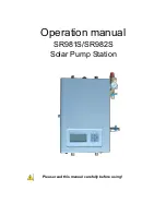
Страница 1: ...SR981S SR982S operation manual of solar pump station Page 0 of 85 Operation manual SR981S SR982S Solar Pump Station Please read this manual carefully before using ...

Страница 2: ...k week 15 6 4 Manu structure 16 6 5 Menu description 17 6 6 System overview 19 6 7 System description 20 System 1 Standard system 1 tank 20 System 2 1 tank 1 solid fuel boiler 21 System 3 1 tank T valve to heat tank in layer 22 System 4 2 tanks controlled by pump logic 23 System 5 2 tanks controlled by thermal enegy transfer logic 24 System 6 2 tanks controlled by T valve logic 25 System 7 East We...

Страница 3: ...ture difference for solar circuit pump 45 8 4 TEMP Temperature main menu 46 8 4 1 EMOF Maximum switch off temperature of collector for collector emergency close function 47 8 4 2 CMX Maximum limited temperature of collector collector cooling function 48 8 4 3 CMN Low temperature protection of collector 49 8 4 4 CFR frost protection temperature of collector 50 8 4 5 REC Recooling temperature of tan...

Страница 4: ...de selection 61 8 5 4 1 n2MN Pump 2 speed adjustment RPM 62 8 5 4 2 DT2S Standard temperature difference of pump 2 for pump 2 speed adjustment 63 8 5 4 3 RIS2 Gain for circulation pump 2 for pump 2 speed adjustment 63 8 5 10 OHQM Thermal energy measuring 63 8 5 9 FTYPE Flow meter type selection 64 8 5 9 FTYP2 Flow meter type selection 65 8 5 10 1 FMAX Flow rate 65 8 5 10 2 MEDT Type of heat transf...

Страница 5: ...liday function 76 8 11 Manual heating 77 8 12 Temperature checking function 78 9 Protection function 78 9 1 Memory protection 78 9 2 Screen protection 78 9 3 Pump P1 P2 dry running protection 78 10 Trouble shooting 79 10 1 Trouble protection 79 10 2 Trouble checking 79 11 Quality Guarantee 81 12 Product specification 82 13 Package list 82 14 Device matched to this pump station 83 ...

Страница 6: ...l and follow the instructions contained herein 1 3 Liability waiver The manufacturer can t monitor the compliance with these instructions or the circumstances and methods used for installation operation utilization and maintenance of this pump station Improper installation can cause damages to material and person This is the reason why we do not take over responsibility and liability for losses da...

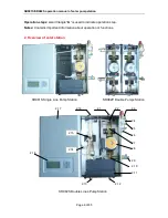
Страница 7: ...ed to indicate operation step Notes Contains important information about operation or functions 2 Overview of solar station SR981S Single Line Pump Station SR982P Double Pumps Station 2 2 2 13 2 1 2 3 2 4 2 6 2 7 2 8 2 12 2 9 2 10 2 11 2 16 2 18 2 17 2 5 2 14 2 15 2 12 5 SR982S Double Lines Pump Station ...

Страница 8: ...d automatic combined air separator not on SR981S single pipe pump station 2 15 Sensor on the collector return pipe high temperature NTC10K B 3950 not on SR981S single pipe pump station 2 16 Collector return pipe connection male thread G1 2 from collector not on SR981S single pipe pump station 2 17 Front cover of pump station 2 18 Display and control panel of built in controller 2 19 Specification ...

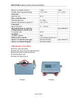
Страница 9: ...ge 0 1 20L min Manual automatic air separator Not on SR981S Filling draining connection unit Connection size G1 2 Insulation Insulation material EPS Built in solar controller see controller manual part Sensor on collector return pipe NTC10K B 3950 Not on SR981S Sensor on collector flow pipe NTC10K B 3950 3 Mounting the solar station Drill the upper fixing hole Fasten the screw hang the station Pic...

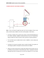
Страница 10: ... may only be performed by properly qualified and authorized personnel with a generally recognized qualification The solar station must be installed indoors prior to installation remove sealing caps from solar station According to the manual of expansion vessel to install and adjust it the pipeline for connecting pump station and expansion vessel should be not insulated Safety valve Risk of scaldin...

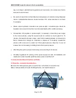
Страница 11: ...g the manual mode of controller to circuit system for 15 minutes then switch off power supply solar fluid is heated gradually air dissolved in fluid is released out through air separator to release air If necessary repeats this process until no more air is vented out If the system pressure drops due to over air release then it is necessary to refilling fluid to the required pressure After filling ...

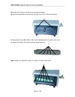
Страница 12: ...on box downwards parallel Loosen the protection screw picture B open the cover of terminal upwards Using proper tools like knife to take out the plastic picture C piece wires can penetrate connection terminal through pre prepared holes Note Please use delivered clamps to fix wires correctly Picture D D ...

Страница 13: ...uipped with 1 5meters silicon cable and suitable for all weather conditions the cable is temperature resistant up to 280o C not necessary to distinguish the positive and negative polarity of the sensor connection Only original factory equipped NTC10K B 3950 temperature sensors are approved for using with tank and pipe it is equipped with 1 5mr PVC cable and the cable is temperature resistant up to...

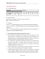
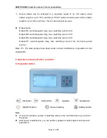
Страница 14: ...ching current 3 5A Output R3 electromagnetic relay max switching current 3 5A Output H1 electromagnetic relay max switching current 3 5A for back up heat source Note P1 P2 solar pumps have been wired on built controller so no position on the output ports 6 Operation manual of built in controller 6 1 Operation button Set button Exit confirm upwards downwards ON OFF button manual heating Holiday but...

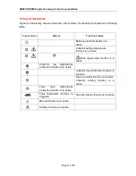
Страница 15: ... Collector safety temperature function is in active Tank urgent stop function is in active Collector low temperature protection function is in active Collector frost protection function is in active Tank re cooling function is in active Collector cooling function is in active Tank high temperature protection function is in active Tank thermostat function is triggered Tank thermostat function is in...

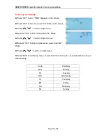
Страница 16: ... screen Press button to adjust hour Repress SET button minute area 00 blinks Press button to adjust minute Repress SET button to adjust week week area MO blinks Press button to adjust week Press ESC to exit setup menu or wait for 20 seconds to exit set parameters are saved automatically Code Weekday MO Monday TU Tuesday WE Wednesday TH Thursday FR Friday SA Saturday SU Sunday ...

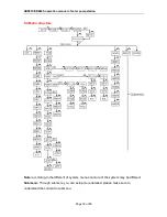
Страница 17: ... pump station Page 16 of 85 6 4 Manu structure Note according to the different of system menu structure of the system may be different Submenu Through submenu you can setup more detailed please make sure to understand the content in submenu ...

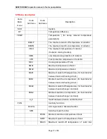
Страница 18: ...ng temperature of Tank SMX1 Maximum temperature of tank 1 SMX2 Maximum temperature of tank 2 MAX1 Maximum switch off temperature for heat transfer between tank and heating circuit MIN1 Minimum switch on temperature for heat transfer between tank and heating circuit MAX2 Maximum switch off temperature for heat transfer between heat exchanger and tank MIN2 Minimum switch on temperature for heat tran...

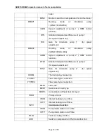
Страница 19: ...ed adjustment of pump 2 RPM control function DT2S Standard temperature difference of pump 2 for speed adjustment RIS2 Gain for circulation pump 2 for speed adjustment OHQM Thermal energy measuring FTYPE1 Flow meter type 1 selection FTYPE2 Flow meter type 2 selection FMAX Flow rate MEDT Heat transfer liquid type MED Concentration of heat transfer liquid PRIO Priority of tank tRUN Interval heating r...

Страница 20: ...ation manual of solar pump station Page 19 of 85 AHF Switch off temperature of thermostat function BYPR Bypass high temperature HDN Manual controlling REST Recovery to factory set PASS Password setup 6 6 System overview ...

Страница 21: ...rence DT1F or the temperature of storage tank reaches its preset maximum storage temperature then the solar circuit pump P1 is switched off Input ports Description Output ports Description T1 Sensor of Collector P1 Pump for solar circuit P1 T2 Sensor on the bottom part of tank T3 Sensor on the top part of tank H1 Back up heat resource T6 DHW sensor R3 Pump for DHW circuit T7 Sensor on the return p...

Страница 22: ...e solar circuit pump P1 is switched off Input ports Description Output ports Description T1 Sensor of Collector P1 Pump for solar circuit T2 Sensor on the bottom part of tank T3 Sensor on the top part of tank H1 Back up heat resource T5 Sensor on the solid fuel boiler R2 Pump for solid fuel boiler T6 DHW sensor R3 Pump for DHW circuit T7 Sensor on the return pipe T8 Sensor on the flow pipe SR981S ...

Страница 23: ...is corresponding DT2F or the tank temperature reaches to its maximum value then P1 R1 are ceased Tank priority logic will decide to heat bottom part of tank firstly Input ports Description Output ports Description T1 Sensor of Collector P1 Pump for solar circuit T2 Sensor on the bottom part of tank H1 Back up heat resource T3 Sensor on the top part of tank R1 For T valve to heat tank different par...

Страница 24: ...ure reaches to its preset maximum value or when temperature difference T1 T2 corresponding DT1F T1 T4 corresponding DT2F drops to the preset switch off value then P1 and P2 are ceased Tank priority logic will decide to heat tank1 firstly Input ports Description Output ports Description T1 Sensor of Collector P1 Pump 1 for tank 1 s solar circuit T2 Sensor on the bottom part of tank 1 P2 Pump 2 for ...

Страница 25: ...y from tank1 to tank 2 See 8 4 8 8 4 9 items to know detailed operations Input ports Description Output ports Description T1 Sensor of Collector P1 Pump 1 for tank 1 s solar circuit T2 Sensor on the bottom part of tank 1 P2 Pump 2 for thermal energy transfer from tank 1 to tank2 T3 Sensor on the top part of tank 2 H1 Back up heat resource T4 Sensor on the bottom part of tank 2 T6 DHW sensor R3 Pum...

Страница 26: ...is heated until tank s temperature reaches to its preset maximum value or when temperature difference T1 T2 corresponding DT1F T1 T4 corresponding DT2F drops to the preset switch off value then P1 and R1 are ceased Tank priority logic will decide to heat tank1 firstly Input ports Description Output ports Description T1 Sensor of Collector P1 Pump 1 for tank 1 s solar circuit T2 Sensor on the botto...

Страница 27: ...t ports Description T0 Sensor of west collector array P1 Pump 1 for collector array circuit T1 Sensor of east collector array P2 Pump 2 for collector array circuit T2 Sensor on the bottom part of tank T3 Sensor on the top part of tank H1 Back up heat resource T6 DHW sensor R3 Pump for DHW circuit T7 Sensor on the return pipe T8 Sensor on the flow pipe SR981S no List of available auxiliary function...

Страница 28: ...when temperature difference drops to the switch off value then P1 R1 is ceased Input ports Description Output ports Description T0 Sensor of west collector array T1 Sensor of east collector array P1 Pump 1 for collector array circuit T2 Sensor on the bottom part of tank R1 For T valve T3 Sensor on the top part of tank H1 Back up heat resource T6 DHW sensor R3 Pump for DHW circuit T7 Sensor on the ...

Страница 29: ...collector array they keeps running until tank temperature reaches its maximum value or when temperature difference T0 T1 and T2 corresponding DT1F T0 T1 and T4 corresponding DT2F drops to the switch off value then P1 P2 R1 is ceased Input ports Description Output ports Description T0 Sensor of west collector array T1 Sensor of east collector array P1 Pump 1 for collector array circuit T2 Sensor on...

Страница 30: ...erature difference between T3 T6 DT2O DT2F is used to control T valve R1 When T3 T4 are not installed then temperature difference between T2 T6 DT2O DT2F is used to control T valve R1 See detailed in 8 4 8 8 4 9 Input ports Description Output ports Description T1 Sensor of collector array T2 Sensor on the bottom part of tank P1 Pump 1 for collector array T3 Sensor on the top part of tank H1 Back u...

Страница 31: ...erence between T4 and T6 DT2O DT2F to control T valve R1 to heat the heating return by solar Note when T4 is not installed then temperature difference between T3 T6 DT2O DT2F is used to control T valve R1 When T3 T4 are not installed then temperature difference between T2 T6 DT2O DT2F is used to control T valve R1 See detailed in 8 4 8 8 4 9 Input ports Description Output ports Description T0 Sens...

Страница 32: ...ature difference reaches its switch on value DT1O then corresponding pump P1 is triggered tank is heated until tank temperature reaches its maximum value or when temperature difference DT1F drops to the switch off value then P1 is ceased Another temperature difference between T4 and T2 DT1O DT1F to control pump P2 to heat tank Note when T4 is not installed then temperature difference between T1 of...

Страница 33: ...in advance System 13 2 tanks controlled by T valve logic T valve for return heating Description Controller compares the temperature between T1 of collector array and T2 of tank 1 or T4 of tank 2 when temperature difference reaches its switch on value T1 T2 corresponding DT1O T1 T4 corresponding DT2O then pump P1 is triggered and simultaneously T valve switches to its direction to heat the correspo...

Страница 34: ...mp logic T valve for return heating Description Controller compares the temperature between T1 of collector array and T2 of tank 1 or T4 of tank 2 when temperature difference reaches its switch on value T1 T2 corresponding DT1O T1 T4 corresponding DT2O then pump P1 P2 are triggered tank is heated until tank temperature reaches its maximum value or when temperature difference T1 T2 corresponding DT...

Страница 35: ...alve logic heat transfer between 2 tanks Description Controller compares the temperature between T1 of collector array and T2 of tank 1 or T4 of tank 2 when temperature difference reaches its switch on value T1 T2 corresponding DT1O T1 T4 corresponding DT2O then pump P1 is triggered and simultaneously T valve switches to its direction to heat the corresponding tank tank is heated until tank temper...

Страница 36: ...1 circuit T2 Sensor on the bottom part of tank 1 P2 Pump 1 for heat transfer from tank 1 to tank 2 T3 Sensor on the top part of tank 1 H1 Back up heat resource T4 Sensor on the bottom part of tank 2 R1 T valve for tank switch T5 Sensor on the top part of tank 2 T6 DHW sensor R3 Pump for DHW circuit T7 Sensor on the return pipe T8 Sensor on the flow pipe SR981S no ...

Страница 37: ...ion manual of solar pump station Page 36 of 85 6 8 East west collector array with double pumps station If user needs a double pump then it is possible to order double pumps station see this picture Type SR982P Type SR982P ...

Страница 38: ...00 and ends also at 10 00 am it means no back up heating in this time The third time section back up heating function starts at 17 00 and ends at 22 00 pm Within this time section default switch on temperature is 50o C default switch off temperature is 55 o C The switch on temperature adjustable range 10 o C OFF 2 o C The switch off temperature adjustable range ON 2 o C 80 o C If you want to shut ...

Страница 39: ...our 04 blinks on the screen the switch on time and temperature for the first time heating function can be set Press button to adjust hour Repress SET button minute 00 blinks on the screen Press button to adjust minute of time Repress SET button temperature 40o C blinks on the screen Press button to set the switch on temperature of heating then press ESC to exit and confirm setting Press button tH ...

Страница 40: ...0 shows on the screen access the submenu of the switch off time and temperature for the second time heating function Press SET button again hour 10 blinks on the screen Press button to adjust hour of time Repress SET button minute 00 blinks on the screen Press button to adjust minute of time Repress SET button temperature 55o C blinks on the screen Press button to set the switch off temperature of...

Страница 41: ...links on the screen Press button to set the switch off temperature of heating Then press ESC to exit this submenu or waiting for 20 seconds to exit this menu automatically value of the parameters are saved automatically Note when no gas or oil boiler is connected to the solar system electrical heater can be installed as back up device when electrical heater is in stand by status sign shows on the ...

Страница 42: ...ou can set the temperature and time to run the DHW pump DHW Temperature control description This controller has an output to run the DHW circulation pump which can be controlled by temperature in this case this function needs an extra circuit pump connect with output R3 and an extra temperature sensor connect with input T6 which mounted on the hot water return pipe When the measured temperature T6...

Страница 43: ...control mode If it is necessary to install T6 sensor in order to avoid measuring error please be sure to install it at place minimum 1 5 m far away to tank Setup steps Under stand by status access tCYC menu Press SET button to enter the tCYC menu tC 1o 05 00 shows on the screen access the submenu of the switch on time for the first time section Press SET button hour 05 blinks on the screen Press b...

Страница 44: ...p then press ESC to confirm the parameters and to exit this setup Press button tC 2F 13 00 shows on the screen access the submenu of the switch off time for the second time section Press SET button again hour 13 blinks on the screen Press button to adjust hour of time Repress SET button minute 00 blinks on the screen Press button to adjust minute of time Repress SET button minute 15Min blinks on t...

Страница 45: ...eters are saved automatically Note above is the setting steps for time control mode temperature control mode is same like these steps 8 Functions operation and parameter setup engineer grade 8 1 Access main menu Under standby status Press SET button and then press until PWD 0000 displays on the screen Press SET button the left figure flashes to ask for entering password factory set password 0000 P...

Страница 46: ...or example the switch on DT is 8o C switch off DT is 4o C if the temperature on the bottom part of storage is 20o C then just when collector temperature rises up to 28o C pump is triggered and when collector temperature drops to 24o C pump is ceased Note to avoid mistake the minimum difference between two temperature differences ΔTon ΔToff is set as 2 o C Setup switch on temperature difference Und...

Страница 47: ...in menu Paragra ph Tem Code Function of temperature Adjustable range Factor y set Function exit tem 8 4 1 EMOF Maximum switch off temperature of collector ON 3 o C 200 o C 130 o C 8 4 1 EMON Maximum switch on temperature of collector OFF 3 o C 197 o C 120 o C 8 4 2 CMX Maximum limited temperature of collector collector cooling function 90 o C 180 o C 110 o C 107 o C 8 4 3 CMN Low temperature prote...

Страница 48: ...set is 120o C solar circuit pump will be recovered to standby and collector emergency close function is deactivated EMOF Maximum switch off temperature of collector Setup steps To access main menu TEMP then select submenu EMOF EMOF 130o C shows on the screen Press SET button parameter 130 o C flashes Press button to adjust this maximum switch off temperature adjust range EMON 3 o C 200 o C factory...

Страница 49: ...ture solar circuit pump is ceased compulsively even the temperature difference is satisfied then when more solar irradiation shines in as a result collector temperature will rise continuously temperature of collector maybe rise up to the evaporated temperature of heat fluid this phenomenon names collector overheat it should be avoided Through set the Maximum limited collector temperature collector...

Страница 50: ...tor Description When the actual temperature of collector is below the preset CMN temperature solar circuit pump is ceased even when the temperature difference between collector and tank exceeds switch on temperature difference solar pump doesn t work yet When the temperature of collector is 2o C higher than the preset CMN temperature solar circuit pump is recovered to standby controller exits this...

Страница 51: ...This function is used in system which uses water as heat transfer liquid to avoid the freezing of solar heat transfer fluid Setup steps To access main menu TEMP then select submenu CFR CFR shows on the screen default set is off Press SET button default off blinks Repress SET button to activate or deactivate this function Press button to adjust the temperature of frost protection function adjustabl...

Страница 52: ... is REC ON Press ESC button to exit the menu or wait for 20 seconds to exit parameters are saved automatically REC sign blinks on the screen it indicates that this function is activated 8 4 6 SMX1 Maximum temperature of tank 1 Description When the DT between collector T1 and tank T2 meets the switch on DT of circulation solar pump is triggered but in order to avoid the high temperature inside tank...

Страница 53: ...adjustable range is 2 o C 95 o C default set is 60 o C Press SET button to activate and deactivate this function if function deactivated SMX 2 displays on the screen Press ESC button to exit the menu or wait for 20 seconds to exit parameters are saved automatically 8 4 8 MAX1 Maximum switch off temperature for heat transfer between tank and heat return Description Example with system 10 When tempe...

Страница 54: ...button parameter 30 o C blinks Press button to adjust the value of maximum temperature of tank adjustable range is 10 o C MAX1 2o C default set is 30 o C Press ESC button to exit the menu or wait for 20 seconds to exit parameters are saved automatically 8 4 10 MAX2 Maximum switch off temperature for heat transfer between heat exchanger and tank Description Example with system 12 In the case that c...

Страница 55: ...changer and tank Setup steps To access main menu TEMP then select submenu MIN2 MAX2 30 o C shows on the screen Press SET button parameter 30 o C blinks Press button to adjust the value of maximum temperature of tank adjustable range is 10 o C MAX2 2o C default set is 30 o C Press ESC button to exit the menu or wait for 20 seconds to exit parameters are saved automatically 8 4 12 C F Switch between...

Страница 56: ...SFB Switch on off of the solid fuel boiler OFF ON OFF 8 5 2 1 SFON Minimum switch on temperature of tank 10 o C SFOF 2 o C 50 o C 8 5 2 2 SFOF Maximum switch off temperature of tank SFON 2 o C 80 o C 55 o C 8 5 2 3 MAX3 Maximum switch off temperature of solid fuel boiler MIN3 2 o C 95 o C 60 o C 8 5 2 4 MIN3 Minimum switch on temperature of solid fuel boiler 10 o C MAX3 2 o C 30 o C 8 5 3 PUMP1 P1...

Страница 57: ... run on time 1 30 minute 15minute 8 5 11 2 tSTP Interval heating run off time 1 30 minute 2 minute 8 5 12 INTV Pump Intermission function ON OFF OFF 8 5 12 1 IRUN Pump interval run on time 2 60 minute 30minute 8 5 12 2 ISTP Pump interval run off time 5 120 seconds 15 seconds 8 5 13 COOL Tank cooling function 5 o C 120 o C 95 o C 8 5 14 AHO Switch on temperature of thermostat function 0 95 o C 50 o...

Страница 58: ...rature of solid fuel boiler T5 is between its minimum and maximum temperature MIN 3 and MAX3 then solid fuel boiler R2 is triggered when tank temperature T3 rises up to the switch off temperature of solid fuel boiler SFOF or when temperature of solid fuel boiler T5 exceeds the scope of its MIN3 and MAX3 then solid fuel boiler is ceased Note The value of MIN3 should be minimum 1o C higher than valu...

Страница 59: ... Press SET button 55 o C blinks Press button to adjust temperature value adjustable range ON 2 o C 80 o C default set is 55 o C Press ESC button to exit the menu or wait for 20 seconds to exit parameters are saved automatically 8 5 2 3 MAX3 Maximum switch off temperature of solid fuel boiler Select MAX3 submenu MAX3 60 o C displays on the screen Press SET button 60o C blinks Press button to adjust...

Страница 60: ... the menu PUMP1 ONOF shows and blinks on the screen factory set is ON OF mode Press button PUMP1 PLUS shows on the screen then pump output is pulse controlled Press button PUMP1 HE A shows on the screen then pump output is high efficiency mode RPM controlled Press ESC button to exit the menu or wait for 20 seconds to exit parameters are saved automatically Note when pump mode is set as PUMP1 HE A ...

Страница 61: ...cally parameters are saved automatically 8 5 3 2 DTS Standard temperature difference of pump 1 for pump 1 speed adjustment Description When the temperature difference between collector and tank meets the switch on temperature difference solar pump starts to work subsequently pump speed reaches to its minimum speed of 30 in 20 seconds And then controller checks temperature continuously when a stand...

Страница 62: ...ble range 1 o C 20 o C factory set is 1o C Press ESC button to exit the menu or wait for 20 seconds to exit parameters are saved automatically 8 5 4 PUMP2 P2 pump operation mode selection Description Pump output mode can be configured to function as one of below three modes ON OF mode for normal pump switch on off mode PLUS mode for normal pump pulse control HEA mode mode for high efficiency pump ...

Страница 63: ...enu and when you set nMIN value of 100 then this output becomes on off control mode Normal ONOF switch output circuit pump speed control RPM is deactivated pump is operated with a fixed speed and flow rate is not changed HE A control output speed control is activated the control system attempts to maintain a constant temperature difference between collector and tank and as a result the pump perfor...

Страница 64: ...s on the screen Press button to adjust standard RIS2 adjustable range 1o C 20 o C factory set is 1o C Press ESC button to exit the menu or wait for 20 seconds to exit parameters are saved automatically 8 5 10 OHQM Thermal energy measuring Description Controller has function of thermal energy measuring it can measure the energy which is transferred from collector to tank For the sake of measuring t...

Страница 65: ...l energy of current day DKWH XX SET displays on the screen Press SET button for 3 seconds buzzer makes 3 times du the daily thermal energy is cleared and daily thermal energy is reset to 00 Press button select to check accumulative thermal energy KWH XX or MWH XX Set displays on the screen Press SET button for 3 seconds buzzer makes 3 times du the sum of thermal energy is cleared and accumulative ...

Страница 66: ...nical flow meter 02 electronic flow meter Select FTYP2 submenu FTYP2 01 displays on the screen Press SET button 01 blinks on the screen Press button to adjust flow meter type adjustable range 01 or 02 Press ESC button to exit the menu or wait for 20 seconds to exit parameters are saved automatically 8 5 10 1 FMAX Flow rate FAMX Flow rate L min adjustable range 0 1 20 L min increase rate 0 1L per b...

Страница 67: ...nds to exit parameters are saved automatically 8 5 10 3 MED Concentration of heat transfer liquid MED Concentration of heat transfer liquid volume percentage depending on the type of heat transfer liquid adjustable range 20 70 factory set 40 Setup steps To select submenu MED MED 40 displays on screen Press SET button parameter 40 blinks on the screen Press button to adjust concentration adjustable...

Страница 68: ...ing lasts 2 minutes every time These 2 parameters are possible to be changed Tank priority function is used in the system with 2 tanks or tank is heated in layer along the body of tank by priority selection thermal energy can be divided into 2 tanks This controller has several different priority logics 1 Tank priority logic 01 and 02 2 Continuance heating Su1 and Su2 3 Parallel heating 0 Select PR...

Страница 69: ...bmenu tRUN tRUN 15 displays on the screen Press SET button parameter 15 displays and blinks factory set is 15 seconds Press button to adjust time adjustable range 01 30 minutes factory set is 15 minutes Press ESC button to exit the menu or wait for 20 seconds to exit parameters are saved automatically 8 5 11 2 tSTP Intermission heating run off time Setup steps To select submenu tSTP tSTP 02 displa...

Страница 70: ...since switch on DT is not reached in order to measure the actual temperature of collector solar pump is triggered to run for 15 seconds it is set by IRUN in every 30 minutes it is set by ISTP as the result the hot water inside the collector can flow to the pipeline where sensor is mounted and the actual temperature of collector can be measured and controller can monitor whether the temperature dif...

Страница 71: ...econds to exit parameters are saved automatically 8 5 13 COOL Tank cooling function Description Tank cooling function is independent from solar system it is used to transfer the extra thermal energy from tank to other heat release device and as a result tank temperature can be kept at a constant value So for this function an extra pump R1 should be installed in the system corresponding tank is tan...

Страница 72: ...function is enabled Application example 8 5 14 AHO Automatical thermostat function Automatically thermostat function is independent from solar system it is used to release the extra heat to reduce the tank temperature or to trigger back up heater to heat tank to the desired temperature This function needs an electromagnetic valve or circulation pump R1 corresponding temperature is T4 Note AHO AHF ...

Страница 73: ...stat function is activated 8 5 15 BYPR Bypass function high temperature Description By bypass electromagnetic valve R1 detailed see 6 7 system description collector is switched either to heat tank or to preheat the pipe between collector and tank first of all temperature difference between collector T1 and tank T2 should meet the switch on temperature difference DT1O then When bypass temperature T...

Страница 74: ...nly for reference Note the one of three functions BYPR AHO COOL is activated then the rest 2 functions are deactivated automatically 8 6 HND Manual control When using this controller first time or when debugging this controller outputs of this controller P1 P2 R1 R2 R3 H1 can be triggered manually with On OFF control Setup steps To access main menu HND Press SET button HND1 off displays on the scr...

Страница 75: ...on HND3 on displays on the screen R1 output is switched on Repress SET again HND3 off displays R1 output is switched off Press ESC to exit setup R1 Press button HND4 off displays on the screen R2 output manually set Press SET button HND4 on displays on the screen R2 output is switched on Repress SET again HND4 off displays R2 output is switched off Press ESC to exit setup R2 Press button HND5 off ...

Страница 76: ...the left figure blinks ask for entering current password factory set is 0000 Press button to enter the first figure Repress SET button the second figure blinks Press button to enter the second figure Repress SET button the third figure blinks Press button to enter the third figure Repress SET button the fourth figure blinks Press button to enter the fourth figure Press SET button PWDN 0000 shows o...

Страница 77: ...se SET button and wait for display recovery to initial interface that means controller recovers to factory set new paramters can be reset now Press ESC button to exit set program or wait for 20 seconds to exit automatically 8 9 ON OFF Controller switch on off button Under standby status Press button for 3 seconds controller is closed OFF displays on the screen Repress button Controller recovers to...

Страница 78: ...tion Electrical heater gas or oil boiler can be as back up devices in a solar system this controller can achieve constant temperature controlling when temperature of top part tank T3 is 2 o C below the preset switch on temperature back up heating will be triggered When the temperature on the top part tank T3 rises up to the preset temperature then heating is ceased Conditions for triggering manual...

Страница 79: ...formation is different Pump accumulated running time Hp current daily absorbed thermal energy DHWH accumulated thermal energy KWH or MWH can only be checked after enabling the OHQM thermal energy measuring function 9 Protection function 9 1 Memory protection In case power failure occurs controller keeps the parameter settings unchanged 9 2 Screen protection When no any press on button for 3 minute...

Страница 80: ...cation T0 T0 sensor problem Sensor wiring short or open Check resistance value or replace T1 T1 sensor problem Sensor wiring short or open Check resistance value or replace T2 T2 sensor problem Sensor wiring short or open Check resistance value or replace T4 T4 sensor problem Sensor wiring short or open Check resistance value or replace T5 T5 sensor problem Sensor wiring short or open Check resist...

Страница 81: ...ly is interrupted Check the pump power cable Solar circuit pump doesn t operate The pump symbol in the display doesn t blink Lighting or blinks The maximum storage tank temperature SMX has been reached or The maximum tank temperature 95 o C reached No fault normal case Lighting or blinks The maximum collector temperature EMOF reached No fault normal case T1 Error code displays on the screen Sensor...

Страница 82: ...000 resistance value o C 0 10 20 30 40 50 60 70 80 90 100 110 120 Ω 1000 1039 1077 1116 1155 1194 1232 1270 1309 1347 1385 1422 1460 NTC 10K B 3950 resistance value o C 0 10 20 30 40 50 60 70 80 90 100 110 120 Ω 33620 20174 12535 8037 5301 3588 2486 1759 1270 933 697 529 407 11 Quality Guarantee Manufacturer provides following quality responsibilities to end users within the period of quality resp...

Страница 83: ...wer of R3 electrical thermal trace 200W Available electrical heater can be controlled H1 1 heater heater power 1500W T0 T1 sensor for collector PT1000 300o C Silicon cable 280o C T2 T3 sensor for tank NTC10K B 3950 135 o C PVC cable 105 o C T4 T5 T6 T7 T8 Optional sensor NTC10K B 3950 135 o C PVC cable 105 o C Ambient temperature 10 50 o C Water proof grade IP42 13 Package list Components Quantity...

Страница 84: ... 304 stainless steel with thread 1 2 OT Size Ф8 200 SR802 Unit for high power electrical heater Dimension 100mm 100mm 65mm Power supply AC180V 264V 50 60Hz Suitable power 4000W Available ambient temperature 10 50o C Waterproof grade IP43 Remote display SR805 with cable Size 130 10 20mm Available ambient temperature 10 o C 50 o C Waterproof grade IP40 See this manual about its application and conne...

Страница 85: ...of 85 SR802 connection diagram SR802连接示意图 Note Switch off power and perform by profession installer Relay L GND N Tank Protection switch PA Protection flexible pipe Electrical heater Controller PA Protection flexible pipe Connect with heater output of controller ...

Отзывы: