SR981S/SR982S operation manual of solar pump station
Page 30 of 85
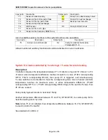
Above mentioned auxiliary functions should be activated in menu in advance.
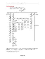
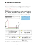
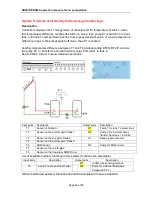
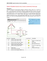
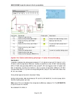
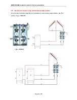
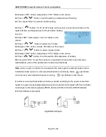
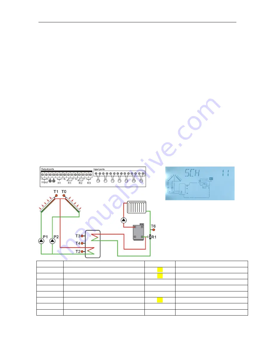
System 11: East/west collector array +1 tank + T-valve controlled by return
heating
Description:
Controller compares the temperature between T0,T1 of west/east collector array and T2 of
tank, when temperature difference reaches its switch-on value (DT1O), then corresponding
pump P1,P2 are triggered, tank is heated until tank temperature reaches its maximum
value or when temperature difference (DT1F) drops to the switch-off value, then P1,P2 are
ceased.
Another temperature difference between T4 and T6 ( DT2O/DT2F) to control T-valve R1 to
heat the heating return by solar.
Note:
when T4 is not installed, then temperature difference between T3, T6 ( DT2O/DT2F)
is used to control T-valve R1
When T3, T4 are not installed, then temperature difference between T2, T6 ( DT2O/DT2F)
is used to control T-valve R1
See detailed in 8.4.8/8.4.9
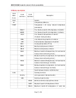
Input ports
Description
Output ports
Description
T0
Sensor of west collector array
P2
Pump 2 for collector array circuit
T1
Sensor of east collector array
P1
Pump 1 for collector array circuit
T2
Sensor on the bottom part of tank
T3
Sensor on the top part of tank
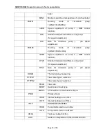
H1
Back-up heat resource
T4
Sensor on the middle part of tank
T6
Sensor on the heating return pipe
R1
T-valve for heat the heating return
T7
Sensor on the return pipe
T8
Sensor on the flow pipe( SR981S no)