


5.5.4.2
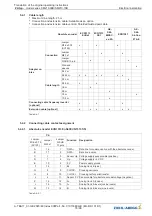
Electromechanical contactors
Brake type
RTW 1000
Operating voltage
207 V
Recti
fi
er
Bridge recti
fi
er*
Table 5-5-4-2
* Bridge recti
fi
er is not included in the scope of supply,
it is available as option from
ZIEHL-ABEGG SE
as item 00154988
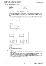
To reduce noises during brake disconnect the brakes should be switched to the alternating current
side (K4), while normal operation. The brakes are switched-o
ff
slower and thus quieter through the
recti
fi
er.
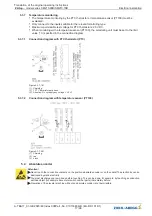
To ensure instantaneous brake application in emergencies, during inspection operation and return
ride use a second contactor (K3), which disconnects the brake from the direct current side. Integrate
this contactor into the safety circuit.
Figure 5-5-4-2-01 - Simpli
fi
ed diagram for brake control
(1) mains
(2) Button two circuit test
(3) / (4)
“
Open brake
”
button
(5) Recti
fi
er
(K3) Brake contactor, activated by safety circuit
(K4) Brake contactor, activated by control or frequency inverter
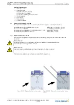
5.5.5
Connection
•
The terminal box for the brake may be removed from the elevator machine and mounted on site for
a better attainability.
•
The brake is only allowed to be supplied with power when fastened to the motor and after having
connected the protective conductor of the motor at the control and the motor side.
•
The brakes must be protected with varistors against overvoltage from switching operations. The
varistor must lie directly on the coil or its connections.
Translation of the original operating instructions
ZAtop
–
model series SM210.60B/SM210.70B
Electrical installation
A-TBA17_01-GB 2023/46 Index 008Part.-No. 01013389-GB (EU-BD 1014/1)
21/96