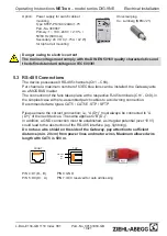
5.4 Pin assignment
Device
Connection
Type
Pins
Manufac-
turer
NETcon
MB/TCP
Gateway
Supply voltage
24 V(DC) +/- 10 %
2-pole
(MC1,5/2-ST-3,5)
1 GND
Phoenix
Lumberg
2 V+ (inner contact)
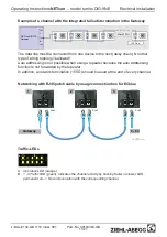
RS-485 network
Pin 7 special function auto
addressing
RJ45
8/8 unshielded
4 B (D-)
5 A (D+)
8 Common/GND
7 C (ID)
Ethernet
RJ45
8/8 shielded
See standard Ethernet
regulations
IEEE 802.3;IEEE 802.3
μ
EIA/TIA 568B
ECblue
Connection
box
Supply voltage
1~200-277 V(AC) +/- 10 %
50/60 Hz
GST 18i3 1,5 mm
2
1 LWieland
2 PE
3 N
RS-485 network
Terminal 1+2 for bus con-
nection
Terminal 3 only for service
Pin 7 Special function
RJ45
8/8 shielded
(Terminal 1+2)
4 B (D-)
5 A (D+)
8 Common/GND
7 C (ID)
6 Communication
6.1 Network installation
The connection of the NETcon MB/TCP Gateway at an Ethernet network is made with
patch lines (e.g. CAT5) to the shielded RJ-45 socket present on the equipment. The
rules of wiring 10/100 Base-T networks are to be kept.
Usually a star wiring is made, i.e. all Ethernet devices are attached in a 10/100 Base-T
network to an Ethernet switch or hub.
In simple cases, the NETcon MB/TCP Gateway can also be attached directly over a
crossover cable at a PC or a router.
6.2 IP Address
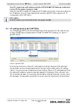
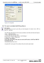
An unique IP address, a subnet mask and a gateway address needs to be assigned for
each device to allow communication within TCP/IP Ethernet networks and can be
realised in one of two ways:
•
Automatic assignment in a network with DHCP- and DNS-Server
•
Manual assignment (in a network without DHCP-Server / it exists so far no net-
work)
Operating Instructions
NETcon
–
model series DIG-9NE
Communication
L-BAL-E134-GB 1118 Index 001
Part.-No. 00163363-GB
12/21


