background image

04

05

1. Fast Installation

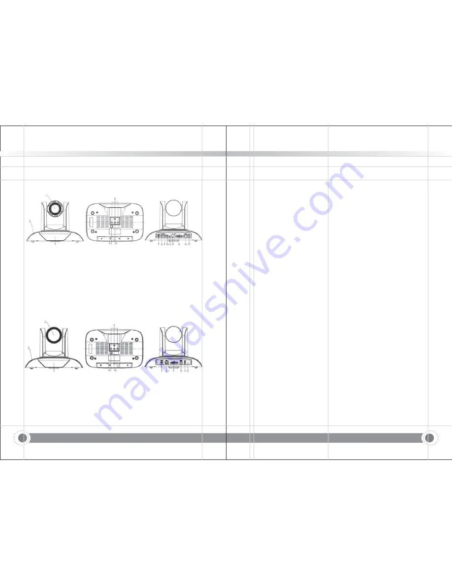
1.1 Camera Interface Explanation

Figure 1.1 Interface of ST (standard) series

1.Camera lens
2.Camera base
3.Remote Controller Receiver light
4.Bottom DIP switch
5.Tripod screw hole
6.Installation Orientation Hole
7.Rotary Switch: Video format select
8.RS232 control interface (input )

9.RS232 control interface (output )
10.RS485 input (left +,right-)
11.Audio Input interface
12.HD-SDI interface
13.DVI-I interface(including HDMI signal)
14.10/100M Network interface
15.DC12V Input Power Supply Socket

1.Camera lens
2.Camera base
3.Remote Controller Receiver light
4.Bottom DIP switch
5.Tripod screw hole
6.Installation Orientation Hole

Figure 1.2. Interface of U3 (USB3.0) series

7.RS232 control interface (input )
8.10/100M Network interface
9.DVI-I interface(including HDMI signal)
10.USB3.0 interface
11.DC12V Input Power Supply Socket
12.Power indicator

1.2 Power on Initial Configuration

Note: If you set preset 0,when Power on initial configuration is completed,the

automatically moves to the preset 0 position.

Note: USB2.0 output and USB3.0 output is the same interface.

1) Power on: connect DC12V power supply adapter with NO.15 showed in Figure

1.1or NO.11 in Figure1.2.

2) initial configuration: Power on with power indicator light on and remote control

receiver light blinking,camera head moves from bottom left to the bottom,and then
go to the HOME position (intermediate position of both horizontal and vertical ),
while the camera module stretches. When remote control receiver light stops
blinking,the self-checking is finished

This series has a variety of video output; ST models have video output from LAN,
DVI (HDMI) and 3G-SDI,while U3 models from LAN,DVI (HDMI),USB3.0 and USB3.0
is compatible with USB2.0.
1) video output from LAN

a. Network cable connection port: ST Model--No.14 in Figure1.1; U3 models--No. 8

in Figure1.2.

b. Webpage Login: open your browser and enter 192.168.5.163 in the address bar

(factory default); press Enter to enter into the login page; click on the “player is
not installed,please download and install!" and follow the installation steps for
installation. Then enter the user name admin and password admin (factory default);
press Enter to enter into the preview page,users can carry out PTZ control, video
recording,playback,configuration and other operations.

2) DVI(HDMI) video output

a. DVI video cable connection: ST models refer to No.13 in Figure1.1; U3 models

refer to No. 9 in Figure1. 2.

b. Connect the camera and the monitor via DVI video cable; video output is available

after camera initial configuration.

3) 3G-SDI video output

a. 3G-SDI video cable connection: ST models refer to No.12 in Figure1.1,U3 models

do not have 3G-SDI interface.

b. Connect the camera and the monitor via 3G-SDI video cable; video output is

available after camera initial configuration.

4) USB3.0 video output

a. USB3.0 video cable connection: ST models do not have USB3.0 interface. U3

models refer to NO.10 in figure1.2.

b. Connect the camera and the monitor via USB3.0 video cable,open video display

software,select image device,and then video output will be available.

5) USB3.0 compatible with USB2.0 output

a. USB3.0 video cable connection:ST models do not have USB3.0 interface. U3

models refer to NO.10 in Figure1. 2.

b. Connect the camera and the monitor via USB3.0 video cable,open video display

software,select image device,and then video output will be available.

1.3 Video output

camera

!"#$

Information and Communication PTZ Camera

!"#$

Information and Communication PTZ Camera

Содержание Z2812U

Страница 1: ...Information and Communication PTZ Camera User Manual...

Страница 2: ...tate camera head by hand otherwise mechanical trouble will occur This series item must put on the smooth desk or platform and it can not be installed slant ways If the camera is installed on TV or com...

Страница 3: ...3 3 Camera setting 3 3 4 P T Z 3 3 5 Video Format 3 3 6 VERSION 3 3 7 RESTORE DEFAULT 02 03 Information and Communication PTZ Camera 4 1 Connecting mode 4 2 IE Log In 4 2 1 Web client 4 2 2 Preview 4...

Страница 4: ...3G SDI while U3 models from LAN DVI HDMI USB3 0 and USB3 0 is compatible with USB2 0 1 video output from LAN a Network cable connection port ST Model No 14 in Figure1 1 U3 models No 8 in Figure1 2 b...

Страница 5: ...ACKET MOUNTING 1 Bracket installation steps 2 Upside down installation steps Note all bracket can not be installed on plasterboard Information and Communication PTZ Camera Information and Communicatio...

Страница 6: ...3 Accessory When you unpack check that all the supplied accessories are included 2 2 Main Features This series camera offers perfect functions superior performance and rich interfaces The features in...

Страница 7: ...with 30 fps compression Support ONVIF RTSP RTMP protocols and RTMP push mode easy to link streaming media server Wowza FMS If the product contains 5G wi fi module you can set up a wireless wi fi conn...

Страница 8: ...oltage DC12V 0 Input Current 1A Max Consumption Max 12W Store Temperature Store Humidity 20 95 Working Temperature Dimension 258mmX172mmX168mm Weight 1 54KG Remote peration O IP Remote Upgrade Reboot...

Страница 9: ...ary DIP Switch Sixteen rotary DIP 0 F interface diagram shown in Figure 2 6 Sixteen rotary DIP 0 F corresponding to the video format as shown in Table 2 4 Note ST model have rotary DIP U3 model is wit...

Страница 10: ...8 NC No Connection B 9 Camera cascade connection method Camera 1 Camera 2 1 DTR 1 DTR 2 DSR 2 DSR 3 TXD 3 TXD 4 GND 4 GND 5 RXD 5 RXD 6 GND 6 GND 7 IR OUT 7 OPEN 8 NC 8 OPEN NO Port Definition 1 DCD D...

Страница 11: ...age device and whether the Universal Serial Bus controllers recognize USB3 0 device After properly identified open the software choose the image device and then it will output image 3 1 1 Power On Ini...

Страница 12: ...he remote controller button the indicator light is flashing release the button the indicator light stops flashing Users can control the pan tilt zoom setting and running preset positions via the IR re...

Страница 13: ...Presets setting Running clearing F1 Camera Address No 1 F2 Camera Address No 2 F3 Camera Address No 3 F4 Camera Address No 4 7 Camera Remote Controller Address Setting 3 3 MENU SETTING 3 3 1 Main menu...

Страница 14: ...ions only available in Auto Iris priority Brightness priority modes 0 15 only available in Auto Iris priority Brightness priority mode 1 25 1 30 1 50 1 60 1 90 1 100 1 120 1 180 1 250 1 350 1 500 1 10...

Страница 15: ...manual Up middle down High middle low 5 NOISE REDUCTION Move the pointer to the NOISE REDUCTION in the Menu click the HOME and enter the NOISE REDUCTION as follow NOISE REDUCTION NR 2D3 NR 3D 5 Dynam...

Страница 16: ...sion 2 0 0 15 2015 12 18 Camera Version 2 0 0 13 2015 12 18 AF Version 2 0 0 6 2015 12 11 Lens 12X 20X Menu Back MCU Version Camera Version AF Version Lens Display MCU version information Display came...

Страница 17: ...irstly open the window of Local Area Connection Properties on computer select the Internet protocol version 4 TCP IPv4 as shown by picture on the left Double click or click the property Internet proto...

Страница 18: ...am When first using IE browser to access the web conferencing camera the login page will appear Playback plug in is not installed please download and install Click on this message download and install...

Страница 19: ...optional 2 U3 series does not have audio input interface only ST series has this configuration 4 2 5 Video configuration 1 Video encoding Code stream Stream Compression Format Video Size Stream Rate...

Страница 20: ...balance sensitivity Red Gain Blue Gain d Image Brightness contrast sharpness black and white mode Gamma DCI Horizontal Flip Vertical Flip and Digital zoom can be set Brightness Contrast Sharpness Blac...

Страница 21: ...an not be modified Click on the Save button it will be valid when display Save successful Note To prevent IP conflicts When modify 3 DNS parameters Preferred DNS server Alternate DNS server 4 GB28181...

Страница 22: ...combination 6 restore on remote controller If use option a the account and passwords will also be restored to default 5 Restore factory setting 6 Reboot 4 2 8 Logout 4 2 9 Wireless network 1 Network s...

Страница 23: ...Completion Message Command packet Note ACK z0 41 FF Returned w he command is accepted hen t Completion z0 51 FF Returned when the command has been executed z camera address 8 Error Messages Command p...

Страница 24: ...FF Direct 8x 01 04 4B 00 00 0p 0q FF pq Iris Position CAM Gain Limit Gain Limit 8x 01 04 2C 0p FF p Gain Positon _ 44 45 Command Function Command packet Note CAM Aperture _ Reset 8x 01 04 02 00 FF Ape...

Страница 25: ...1080P59 94 B 1080i59 94 C 720P59 94 D 1080P29 97 E 720P29 97 Command Function Command packet Note CAM Aperture _ Reset 8x 01 04 02 00 FF Aperture Control Up 8x 01 04 02 02 FF Down 8x 01 04 02 03 FF Di...

Страница 26: ...0 50 00 00 0p 0q FF pq Iris Position CAM_ Gain LimitInq 8x 09 04 2C FF y0 50 0p FF p Gain Positon CAM_ BrightPosInq 8x 09 04 4D FF y0 50 00 00 0p 0q FF pq Bright Position Command Function Command pack...

Страница 27: ...0q FF pq ExpComp Position CAM_ BacklightModeInq 8x 09 04 33 FF y0 50 02 FF On y0 50 03 FF Off CAM_ WDRStrengthInq 8x 09 04 51 FF y0 50 00 00 00 0p FF p WDR Strength CAM_ NRLevel 2D Inq 8x 09 04 53 FF...

Страница 28: ...Position 0xFF Address 0x00 0x51 SUM 0x00 0x00 Query Pan Position Response 0xFF Address 0x00 0x59 Value High Byte Value Low Byte SUM Query Tilt Position 0xFF Address 0x00 0x53 SUM 0x00 0x00 Query Tilt...

Страница 29: ...is consistent b Check whether the control cable is connected properly c Check whether the camera working mode is the normal operating mode see Table 1 2 and Table 1 3 6 1 Camera Maintenance 6 2 Troubl...

Страница 30: ...pyright can not be reproduced 6 Web pages can not log in a Check whether the camera is showing normally b Check whether the network cable is connected properly Ethernet port yellow light flashes to in...

Отзывы: