16
17
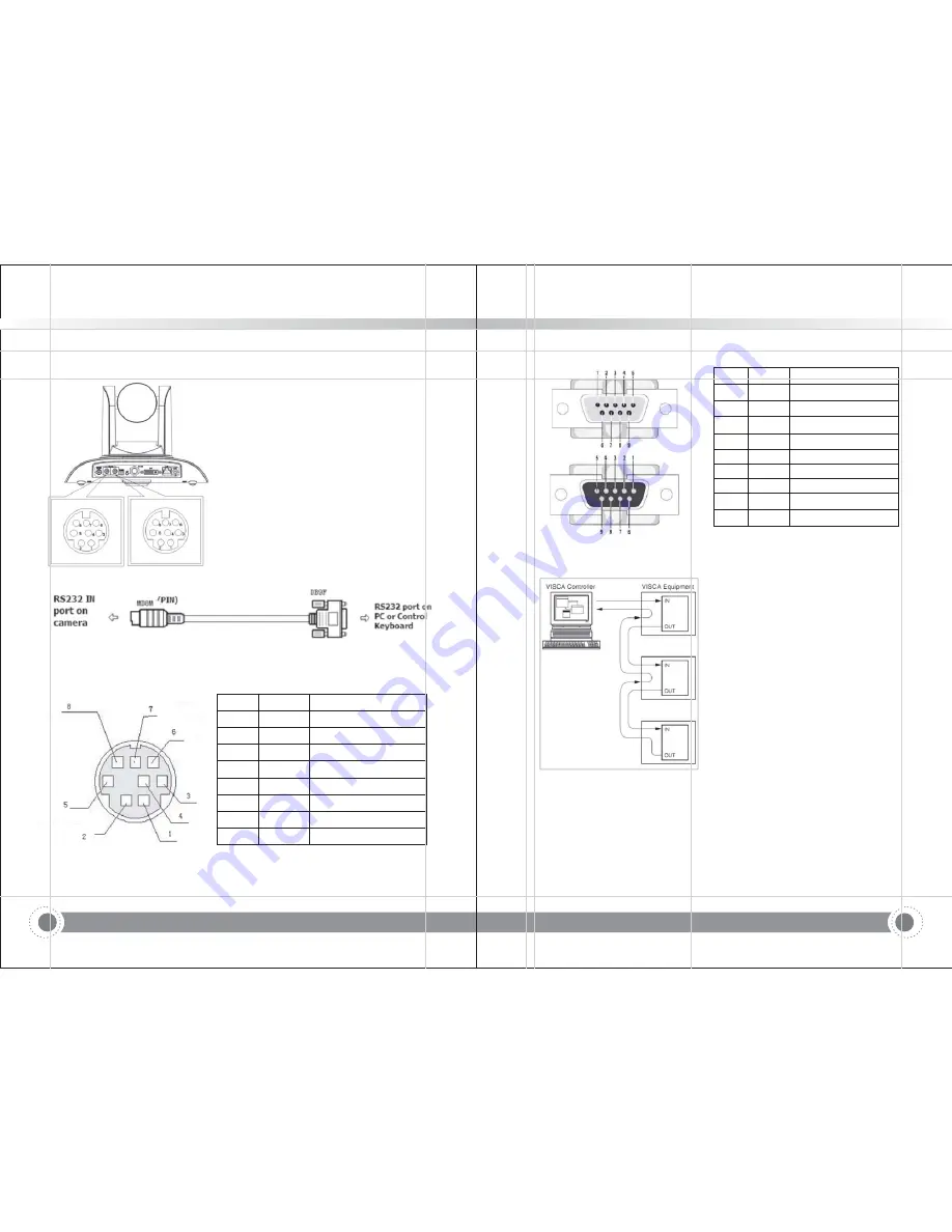
2 4 4 RS 232 interface
. .
-
1 ST
)
model RS-232C interface specification as shown below
Computer or keyboard and
a
camer
connection method
Camera
WindowsD
1 DTR
.
1 DCD
.
2 DSR
.
2 RXD
.
3 TXD
.
3 TXD
.
4 GND
.
4 DTR
.
5 RXD
.
5 GND
.
6 GND
.
6 DSR
.
7 IR
. OUT
7 RTS
.
8 NC
.
8.CTS
.
9 RI
2 RS 232 Mini DIN
e
)
-
-
8-pin Port D finition
NO
P
Definition
.
ort
1
DTR
Data Terminal Ready
2
DSR
Data Set Ready
3
TXD
Transmit Data
4
GND
System Ground
5
RXD
Receive Data
6
GND
System Ground
7
IR OUT
IR Commander Signal
8
NC
No Connection
B 9
-
Camera cascade connection method
Camera 1
Camera 2
1 DTR
1 DTR
.
.
2 DSR
2 DSR
.
.
3 TXD
3 TXD
.
.
4 GND
4 GND
.
.
5 RXD
5 RXD
.
.
6 GND
.
6 GND
.
7 IR
.
OUT
7 OPEN
.
8. NC
8 OPEN
.
NO
Port
Definition
.
1
DCD
Data Carrier Detect
2
RXD
Receive Data
3
TXD
Transmit Data
4
DTR
Data Terminal Ready
5
GND
System Ground
6
DSR
Data Set Ready
7
RTS
Request to Send
8
CTS
Clear to Send
9
RI
Ring Indicator
3) Rs232 (DB9) Port Definition
4) VISCA networking as shown below:
Note: ST model has RS232 input and output interface,so you can cascade as
the above way;
It won't work for U3 model,since U3 model only has RS232
!"#$
Information and Communication PTZ Camera
!"#$
Information and Communication PTZ Camera


