PREMIER QUATRO INSTALLATION MANUAL (Fyreye MKII) Firmware Versions: PANEL 1.84 & LOOP 3.70
Doc No: GLT-215-7-1 Issue: 1.36 Author: NJ/TE DATE: 25/05/2017
32
(b) Level 2 or Installer Password (Default 2222)
Only one level 2 password is permitted by the panel at any time. It is essential that the level 2 password is kept secret from the
panel users (and of course the general public). This 4-digit password, which the installation engineer can select and edit, is required
to set up the site configuration of a panel.
The Level 2 password can be changed as follows:
Turn the key switch clockwise to the Controls Enabled Position. The controls Active LED will light.
Press any key followed by the level 2 password (default is 2222).
Press the
▼
key until
General
is highlighted.
Select
General
and then
Password
. You are now able to enter the password for the 1st authorised user. The LEVEL must be
set to 2 (see top right corner).
The current Level 2 password must be entered before it can be changed to a new password.
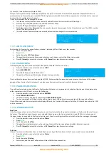
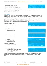
CHANGE PASSWORD LEVEL: <2>
CURRENT PASSWORD : [2222]
NEW PASSWORD : [2468]
[Accept ] [Exit ]
7.1.7 LED FLASH SETUP
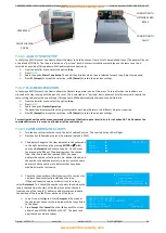
By selecting this function for a specific loop, a device’s indicating LED will flash every few seconds.
Select the option
Loop
Press
ENTER
Select the option
LED Flash Setup
The panel then displays the 4 loops and whether or not they are set to blink. Adjust as required.
Press
F1 (Accept)
to accept the selection, or
F4 (Cancel)
to retain the previous settings.
7.1.8 ENGINEERING
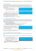
The loop engineering tool is used to check at what quality the data transfer is on a loop.
From the installer menu, select the option
LOOP
.
Select
ENGINEERING
.
Select which loop you would like to check.
The quality of the loop will be displayed below the loop selection.
You should aim to always have your loop quality at 100.0. As the quality of communications decreases, the chance of the system
giving out false alarms or faults increases. It can also cause the response from real events to become delayed.
7.1.9 ENABLE USB CONFIG
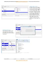
This will be selected when using the Quatro Configuration Software or Loop Inspector. In order to allow the panel to communicate
with a computer via its USB port, carry out the following:
From the installer menu, select the option
GENERAL
.
Select
ENABLE USB CONFIG
The panel will enter and display the message
USB CONFIGURATION
.
You can now plug the USB lead into the quarto display board USB port and communicate with the required software.
(Note: When connected to a computer via the display USB port, the Quatro will display an Earth Fault. It should clear when the USB
cable is removed.)
7.1.10 PRINTER SETUP
Real Time
If the Quatro panel has a printer fitted, this option is used to select whether the panel prints alarms, or faults or both in real time as
they occur. The panel can reprint events over a selectable date range, so the live print can be turned off if this is not convenient.
If a pager system is connected to the Quarto’s printer port, then live printing should be selected to allow the messages to be paged.
From the installer menu, select the option
Printer
Press
ENTER
Select the option
Real Time
The panel then displays whether online printing of alarms & faults are enabled or disabled. Adjust as required.
Press
F1 (Accept)
to accept the selection, or
F4 (Cancel)
to retain the previous settings.
Print Log
If there is a printer installed, then there is the ability to print a log of faults and events that have occurred from a selected date.
From the installer menu, select the option
Printer
Press
ENTER
Select the option
Print Log
Enter a date, and the panel will print events from that date to present day.
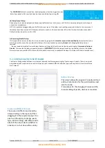
LOOP :<1>
QUALITY 100.0
[Reset ] [Exit ]


