PREMIER QUATRO INSTALLATION MANUAL (Fyreye MKII) Firmware Versions: PANEL 1.84 & LOOP 3.70
Doc No: GLT-215-7-1 Issue: 1.36 Author: NJ/TE DATE: 25/05/2017
19
5.3 MAINS WIRING RECOMMENDATIONS
The Mains supply to the FACP is fixed wiring, using
Fire resisting
3-core cable (Between 1 mm² and 2.5mm²), fed from an isolating
double pole switch fused spur, and fused at 3A.
IT SHOULD NOT BE CONNECTED THROUGH AN RCD.
This should be secure from
unauthorised operation and be marked ‘FIRE ALARM: DO NOT SWITCH OFF’. The supply must be exclusive to the Fire Panel.
MAKE
SURE ANY SPARE ENTRY HOLES ARE COVERED WITH THE GROMMETS PROVIDED.
For information on how to connect Mains to the Panel’s Power Supply PCB, see Section 6.
Also refer to rating information on the mains cover inside the FACP.
5.4 PLANNING CABLE ENTRY
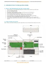
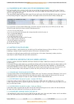
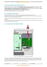
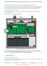
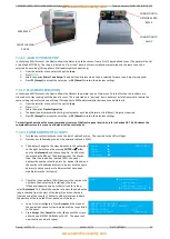
Fig.2 below shows the location of the cable entries to facilitate planning of wiring to be brought to the panel.
The Knock-out cable entries can be easily removed by Tapping with a suitable screwdriver or chisel from outside the control panel
box (Take care not to dent or deform the metal enclosure).
If a grommet is removed, fill the hole with a brass cable gland. If any knockout is removed, but subsequently not used, it should be
covered up.
The 230V AC Mains cable must be fed into the enclosure via one of the cable entries at the top right corner of the back box. (Refer
to “Connecting the Mains Power” in Section 5.1).
5.5 CONNECTING THE MAINS POWER
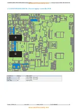
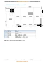
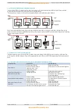
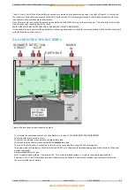
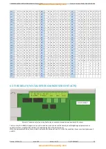
Figure 3: Power Supply PCB layout and Mains connection details
The panel should be connected to mains supply by a 3A rated spur to the fuse box with 1mm2 to 2.5mm2 3-core cables. Nothing
else should be connected to this supply. The cable should be fire resistant. NB It is recommended that the mains cable should pass
twice through the ferrite supplied with the panel, to improve the panel’s immunity to electromagnetic interference. The ferrite
should be positioned between the mains entry port and the power supply cage.

