Fan Coil ‘Analog’
Technical Support:
8
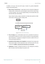
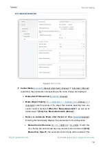
The objects that will store the output control value,
"[FCn] Valve: Control"
(for
fan coil of two pipes) and
"[FCn] Cooling Valve: Control"
and
"[FCn] Heating
Valve: Control"
(for fan coil of four pipes), must be linked to the appropriate
actuator.
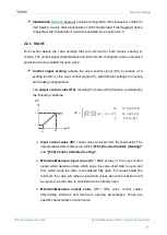
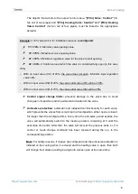
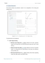
Example: 2-10V valve which, for installation reasons, is configured:
Y1 = 10%
Minimum valve opening value.
Y2 = 75%
Maximum valve opening value.
X1 = 33%
Minimum regulation value for the valve to start opening.
X2 = 66%
Control value at which the valve is considered fully open (in this case
75%).
o
With an input value (VE) of 20%, the valve does not open. Minimum input regulation
value 33%.
o
With an input value (VE) of 40%, the valve outlet value (VS) will be 23.8%.
o
With an input value (VE) of 70%, the valve outlet value (VS) will be 75%.
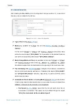
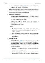
Control signal change limits:
prevents damage to the valve due to small
changes in its position and/or permanent activation of the valve.
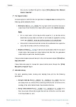
Anti-seize protection:
automatic and
independent functionality for each valve,
which prevents the valves from remaining in a fixed position, either open or closed,
for longer than the configured time. Every time the anti-seize period expires, the
valve will automatically switch to the inverse position, remaining at it until the
execution time ends. After that, the valve will recover the previous state or, if a
control or mode change command has been received during the run, to the
corresponding position.
Note: For safety reasons, if 4 pipes are configured and the anti-seize protection is
initiated on the cooling when it is closed and the heating valve is open, then both
will change their status avoiding having both valves open at the same time.

