


Random Access Adjustment Mode
6-8
206-3612 ZENITH PRO 1200X 151199
Geometry Adjustments
Geometry Adjustments
Geometry Adjustments
Geometry Adjustments
Geometry Adjustments
The geometry adjustments have to be done only on the green image. These adjustments are automatically implemented for the other color images
: Left-right (EW) and Top-Bottom Corrections, Blanking, Horizontal Amplitude, Vertical Amplitude, Vertical Linearity and Horizontal Phase.
Highlight
GEOMETRY by pushing the control disk up or down and press
ENTER
ENTER
ENTER
ENTER
ENTER to display the geometry menu.
Select with or
then <ENTER>
<EXIT> to return.
RANDOM ACCESS
RANDOM ACCESS
RANDOM ACCESS
RANDOM ACCESS
RANDOM ACCESS
ADJUSTMENT MODE
ADJUSTMENT MODE
ADJUSTMENT MODE
ADJUSTMENT MODE
ADJUSTMENT MODE
PICTURE TUNING
GEOMETRY
GEOMETRY
GEOMETRY
GEOMETRY
GEOMETRY
CONVERGENCE
FOCUSING
COLOR SELECT
CONTR. MODULATION
SOFT EDGE
Select with or
then <ENTER>
<EXIT> to return.
GEOMETRY
GEOMETRY
GEOMETRY
GEOMETRY
GEOMETRY
H PHASE
RASTER SHIFT
LEFT-RIGHT (E-W)
LEFT SIDE CORRECTION
TOP-BOTTOM (N-S)
H SIZE
V LINEARITY
V SIZE
BLANKING
ENTER
ENTER
ENTER
ENTER
ENTER will display Geometry menu.
EXIT
EXIT
EXIT
EXIT
EXIT will return to Internal Crosshatch Selection or Setup
Pattern Selection Menu.
ADJUST
ADJUST
ADJUST
ADJUST
ADJUST returns to operational mode.
Within the Geometry Adjustment menu, the following adjustments are
available :
- Horizontal Phase (not for internal # pattern).
- Raster Shift
- Left-Right Corrections
- Left Side Corrections
- Top-Bottom Corrections
- Horizontal Size
- Vertical Linearity
- Vertical Size
- Blanking
The convergence corrections are disabled during geometry correc-
tions. The blanking corrections are only enabled during the blanking
adjustments.
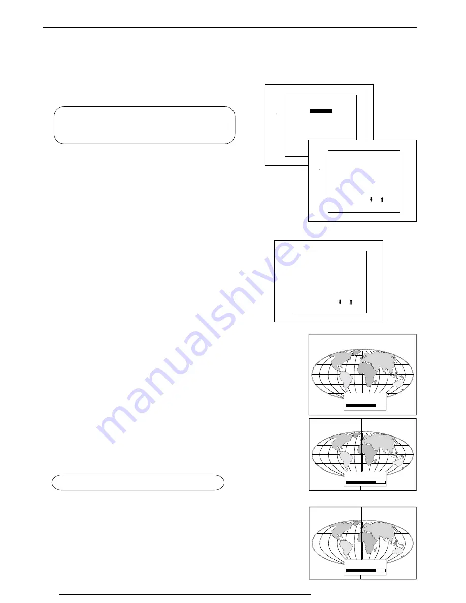
Horizontal Phase Adjustment
Horizontal Phase Adjustment
Horizontal Phase Adjustment
Horizontal Phase Adjustment
Horizontal Phase Adjustment
Push the control disk up or down to highlight
H PHASE on Geometry
menu and then press ENTER
ENTER
ENTER
ENTER
ENTER.
Note : No horizontal phase adjustment is available on the internal #
pattern.
For external sources :
If the raster shift is correctly adjusted, the H Phase text box is projected
in the middle of the raster. At that moment, the "><" icon indicates the
middle of the raster.
Adjust the H Phase control until the middle of the projected image is
equal with the middle of >< icon.
Note :
- If the genlocked pattern wasselected, the external source will be
displayed.
A bar scale and a number indicator (between 0 and 100) on the screen
give a visual indication of the horizontal phase adjustment.
020)5-
70
><
Select with or
then <ENTER>
<EXIT> to return.
GEOMETRY
GEOMETRY
GEOMETRY
GEOMETRY
GEOMETRY
H PHASE
H PHASE
H PHASE
H PHASE
H PHASE
RASTER SHIFT
LEFT-RIGHT (E-W)
LEFT SIDE CORRECTION
TOP-BOTTOM (N-S)
H SIZE
V LINEARITY
V SIZE
BLANKING
020)5-
70
><
ENTER
ENTER
ENTER
ENTER
ENTER continues to geometry menu .
Push the control stick to
the right to correct
Push the control stick to
the left to correct
020)5-
70
><
Содержание PRO1200X
Страница 1: ...PRO1200X OWNER S MANUAL ...
Страница 14: ...Connections 3 6 206 3612 ZENITH PRO 1200X 151199 ...


