background image


Primovert 

Start-Up and Operation 

ZEISS 


12/2014 

415510-7244-001 

39 

3.4


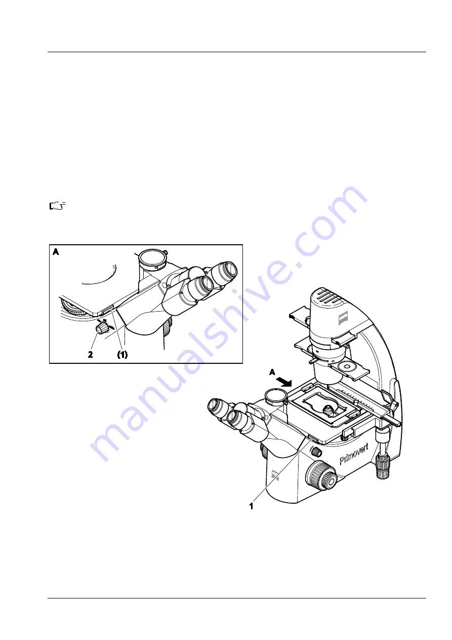
Switching the Microscope On / Off 


Switch on the microscope using the rotary knob (Fig. 28/

2

) (

ON

 or 

AUTO

 position). 


ON 

position:    

The two ON/OFF switches (Fig. 28/

1

) on the specimen stage for quickly switching the transmitted-

light illuminator on and off are inactive. The illuminator remains continuously switched on.  


AUTO 

position:  

The ON/OFF switches (Fig. 28/

1

) for quickly switching the transmitted-light illuminator on and off 

are active. So, the illuminator can be switched off and on again quickly. After an operation time of 
15 minutes, the illuminator switches off automatically and goes to standby mode. Upon actuating 

one of the ON/OFF switches, the illuminator switches on again. When actuating the switch once 
more during operation, the 15-minute period will start again from the beginning. 


Recommendation:


If you want to use the microscope only for a short time, you should use the 

AUTO

 function. 

This saves energy and extends the lifetime of the transmitted-light illuminator. 


Fig. 28 

Switching the microscope on or off 

Содержание Primovert

Страница 1: ...Primovert Operating Manual...

Страница 2: ...red by an update service Unless expressly authorized forwarding and duplication of this document as well as utilization and communication of its contents are not permitted Violations will entail an ob...

Страница 3: ...ting UV Protection Plate onto Primovert iLED 19 3 1 9 Transmitted Light Illuminator Inserting the LED 20 3 1 10 Connecting the Stand with Binocular Tube or Phototube to the Power Supply System 20 3 2...

Страница 4: ...3 9 2 Attaching a Camera to the Stand with Binocular Phototube 44 3 10 Care Maintenance and Troubleshooting 46 3 11 Instrument Care 46 3 12 Troubleshooting on the Microcope 47 3 13 Troubleshooting on...

Страница 5: ...tion is emitted Do not look into the LED beam It can be dangerous to the eyes ATTENTION Disconnect the plug in power unit from line power before opening the microscope ATTENTION This symbol indicates...

Страница 6: ...w The manufacturer of the device is under the legal obligation to take back defective devices 1 5 Operation The microscope including its original accessories must not be used for microscopic technique...

Страница 7: ...connect the power cable before opening the instrument and changing the bulb or LED Wait for the bulb to cool down before replacing it and do not leave fingerprints on the new bulb The instrument may o...

Страница 8: ...their original accessories must not be used for microscopic techniques other than those described in this operating manual The manufacturer cannot assume any liability for other applications Please c...

Страница 9: ...Primovert Notes on Instrument Safety ZEISS 12 2014 415510 7244 001 9 1 7 Warning and Information Labels Fig 1 Warning and information labels on the Primovert...

Страница 10: ...ZEISS Description Primovert 10 415510 7244 001 12 2014 2 DESCRIPTION 2 1 System Overview...

Страница 11: ...Primovert Description ZEISS 12 2014 415510 7244 001 11...

Страница 12: ...integrated HD IP CMOS camera and various interfaces and setting options Stand type Primovert iLED with integrated LED fluorescence unit one channel and binocular phototube Important features of the mi...

Страница 13: ...x and 10x for brightfield and phase contrast as well as LD Plan ACHROMAT objectives with long working distance and magnifications of 20x and 40x for brightfield and phase contrast Preadjusted phase co...

Страница 14: ...agnification of the stand with tube phototube is obtained by multiplying objective magnification by eyepiece magnification e g 40 x 10 400x Numerical aperture multiplied by 1000 e g 0 5 x 1000 500x pr...

Страница 15: ...sport case and put it on the worktable using the handle on the back of the stand Do not hold the microscope on the front side by the eyepiece part but by the neck of the stand between the eyepiece par...

Страница 16: ...er 3 1 4 Inserting the Filter Slider Put the color filter Fig 5 1 or the green interference filter diameter d 45 mm into the opening of the filter slider As the filters are clamped in the filter slide...

Страница 17: ...Fig 7 6 into the specimen stage The metal insert with a bean like opening is to be used to prevent an objective with short working distance e g 40x from colliding with the sample container when being...

Страница 18: ...ert the universal mounting frame M or the mounting frame for 96 position microtiter plates Fig 8 5 into the specimen guide depending on the sample vessel used Make sure that the mounting frame stops p...

Страница 19: ...19 3 1 8 Mounting UV Protection Plate onto Primovert iLED Put the UV protection plate Fig 9 1 on the Primovert fluorescence stand Fix it with the screws Fig 9 2 on both sides 1 UV protection plate 2...

Страница 20: ...ecessary replace the power supply adapter attached to the plug in power unit Fig 10 1 by one of the country specific adapters supplied Fig 10 3 pulling off the existing adapter and inserting the desir...

Страница 21: ...peration ZEISS 12 2014 415510 7244 001 21 3 2 Operating the Microscope 3 2 1 Operational and Functional Elements of the Primovert Microscope Fig 11 Operational elements of Primovert with binocular tub...

Страница 22: ...sing drive right side 11 Rotary knob for adjusting the illumination intensity 12 On off switch for illumination active with rotary knob in AUTO position 13 Tube 14 Binocular part of the tube 15 Eyepie...

Страница 23: ...Primovert Start Up and Operation ZEISS 12 2014 415510 7244 001 23 Fig 12 Operational elements of Primovert HDcam with integrated camera...

Страница 24: ...active with rotary knob in AUTO position 11 Control elements 12 Holder for iPad 13 Lever for adjusting the aperture diaphragm of the condenser 14 Rotary knob for switching the microscope on and off w...

Страница 25: ...Primovert Start Up and Operation ZEISS 12 2014 415510 7244 001 25 Fig 14 Operational elements of Primovert iLED with integrated fluorescence unit...

Страница 26: ...in AUTO position 10 Tube 11 Binocular part of the tube 12 Eyepieces with eyecups 13 Camera port only stand with binocular phototube 14 Lever for adjusting the aperture diaphragm of the condenser 15 R...

Страница 27: ...ing briefly press the snap button to stop recording Press the menu button Fig 15 2 to open the On Screen Display OSD menu Pos No Standard function Function in OSD menu 2 Activate menu Exit menu 3 AWB...

Страница 28: ...The microscope stand has a SD SDHC card port Fig 18 2 at the left side for storing image data see section 3 3 3 1 The following connecting cables are required for use of the ports Item Name Figure Rem...

Страница 29: ...red for approx 5 seconds Table 3 LED status displays 3 3 2 Connect iPad to USB charge port If you want to load the iPad use the USB charge port Fig 17 3 for iPad Connect the iPad via USB cable with th...

Страница 30: ...econd Fig 18 1 to trigger an exposure The images are saved on the SD SDHC card in JPG format Press the snap button Fig 18 1 for 2 seconds to start a video recording Briefly pressing the snap button on...

Страница 31: ...e built in camera is compatible with ZEN or ZEN lite Insert the mini USB plug Fig 19 1 of the USB cable into the USB 2 0 port Fig 19 2 on the reverse side of microscope Insert the USB 2 0 plug Fig 19...

Страница 32: ...1 into the jack on the reverse side of the microscope Fig 20 2 and the monitor projector Fig 20 3 Secure the HDMI plug on the jack on the monitor projector If a monitor projector is used an HDMI DVI a...

Страница 33: ...21 3 on Dynamic Host Configuration Protocol DHCP and will be automatically recognized by Labscope provided the iPad Fig 21 4 is in the same network Consult your network administrator for further guid...

Страница 34: ...contrast Down reduce value Arrow Left Reduce brightness Left Arrow Right Increase brightness Right 4 Index None Go to top tier of menu 5 Live Clear screen of windows Exit menu 6 Input Toggle between...

Страница 35: ...that the white balance applies to the light source and not the main color of the specimen the Push button mode can be set Here the white balance is carried out only once if the AWB OK button is presse...

Страница 36: ...one time automatic adjustment will be carried out when confirmed with OK but then deactivated again Auto level Influences the AET AGC control when Continuous mode is set Extreme left very dark image E...

Страница 37: ...in improved image quality with the same data rate Sharpening Value range 0 to 3 Edge flickering may occur in some HDMI monitors with a default value of 3 but this will disappear with lower values Sna...

Страница 38: ...ngs After confirmation with OK the camera will be restarted This may take several seconds If the OSD menu is not available the factory settings can be reinstated using the short cut Snap AWB OK keep d...

Страница 39: ...ng the transmitted light illuminator on and off are active So the illuminator can be switched off and on again quickly After an operation time of 15 minutes the illuminator switches off automatically...

Страница 40: ...wdriver to the right or left in order to adjust the torque of the coarse drive as desired After finishing work switch off the microscope with the rotary knob Fig 28 2 OFF position Cover the microscope...

Страница 41: ...his end follow this procedure Unscrew the stop Fig 32 5 by hand from the eyepiece Insert the eyepiece pointer Fig 32 4a or the eyepiece micrometer Fig 32 4b into the eyepiece with the coated side faci...

Страница 42: ...f the phase stop according to the drawing in Fig 34 To this end remove one eyepiece and replace it by the diopter Center the phase stop if necessary Fig 34 A by turning the two adjusting screws Fig 33...

Страница 43: ...luminator with LED or the halogen bulb 6 V 30 W allow for a sufficient cool down time and remove the plug in power unit from the socket Press down the clamping lug of the cover Fig 36 1 and remove the...

Страница 44: ...phototube using the four available camera adapters see Section 2 1 Loosen the clamping screw Fig 37 7 and remove the dust cap from the camera port Fig 37 8 of the binocular phototube Attaching a Comp...

Страница 45: ...gradually i e displace the sliding mount with camera on the lens mount in defined steps Zoom the camera lens through from wide angle W to tele position T Carry out this test until the image is format...

Страница 46: ...free cotton cloth or a cloth moistened with water to which you may also add a mild detergent Wipe off stubborn oily or fatty dirt immersion oil fingerprints with cotton cloths or a dust free cotton c...

Страница 47: ...sual acuity or set it to zero when using glasses or contact lenses Objectives has not been correctly screwed in Screw in objectives correctly The 6 V 30 W halogen bulb or the LED source does not light...

Страница 48: ...nce light source or circuit board is defective Contact service person for further checking If necessary change LED source or PCB Replacement requires special tools and can thus not be carried out by t...

Страница 49: ...t formatted Format SD card replace SD card if error message does not disappear Buttons do not react LED flashes red when a button is pressed The buttons are temporarily locked as the camera is being a...

Страница 50: ...monitor Monitor displays an error message that after switch over to 1080p resolution the signal is outside the monitor specifications The monitor may not support a 1080p30 signal Hold down the Menu a...

Страница 51: ...2000 m 10 to 40 C max 75 at 35 C no condensation 800 hPa to 1060 hPa Operating Data Protection class Protection type Electrical safety Pollution degree Overvoltage category Radio interference suppress...

Страница 52: ...to 40x approx 15 to 100 Optical Mechanical Data Stand with stage focusing drives With coarse focusing drive With fine focusing drive Total stage lift 45 mm rev 0 5 mm rev 15 mm Objective change manua...

Страница 53: ...14 2 mm diagonal 0 63x HDMI USB2 0 Ethernet port SD card tiltable 40 80 degree Primovert with integrated fluorescence unit Maximum field of view number Illumination Fluorescent source Transmitted sour...

Страница 54: ...el Amplification 0 18 dB Interfaces USB 2 0 mini USB plug LAN via RJ 45 jack 100 Mbit SD card secure digital 1 32 GB slot for SD and SDHC HDMI 1080p 30 or 720p 60 Remote release IR sensor Duo LED Read...

Отзывы: