22 - EN
EN - 23
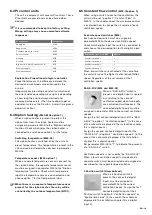
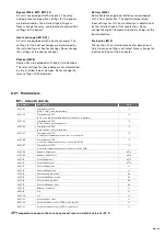
Safety switch time (M10-27)
When the unit is equipped with both a heating and
cooling battery a minimum switch time between the
heating and cooling battery must be set in parameter
M10-27, to ensure that the heater and cooler do not
switch on too soon after each other.
Battery failure (M10-28)
The unit will check the temperatures before and
after the cooler and postheater to check if the
battery is working properly. The allowed minimal
temperature different before and after the battery
can be set in parameter M10-28. The higher the set
temperature difference, the higher the risk of failure.
(The permitted difference is often set at 4˚C.) When
the temperature will not drop fast enough the unit
will display error E38. When the temperature will not
raise fast enough the unit will display error E39.
6.18 Temperature control
(M10)
Comfort temperature (M10-01 option 0, M10-99)
When there are no batteries installed in the unit
it is recommended to use comfort temperature
control.
When the room temperature must be controlled
by one desired preset temperature (comfort
temperature), parameter M10-01 must be set
to option 0 “Tcomfort”. The desired comfort
temperature is preset and can be changed in
parameter M10-99. It is best to set the comfort
temperature to the same temperature as the room
thermostat (of the central heating system).
When possible the unit will use the installed bypass
to reach the desired supply temperature. When the
outdoor temperature becomes too cold the unit
disables the use of the bypass for comfort control.
This temperature is preset and can be altered when
desired in parameter M11-07.
Heatline (M10-01 option 1, M10)
When a battery is installed in the unit it is
recommended to use heatline temperature
control.
When the supply temperature must be controlled by
the outdoor temperature, parameter M10-01 must
be set to option 1 “Outdoor heatline”. The desired
heatline temperatures can be set in parameter M10.
There are 3 points for the heating heatline and 3
points for cooling heatline.
Function
Parameter
Outdoor temperature
Low point heating
M10-02
Function
Parameter
Supply temperature
Low point heating
M10-03
Outdoor temperature
Medium point heating
M10-04
Supply temperature
Medium point heating
M10-05
Outdoor temperature
High point heating
M10-06
Supply temperature
High point heating
M10-07
Function
Parameter
Minimum supply temperature
M10-24
Maximum supply temperature
M10-25
Outdoor temperature
Low point cooling
M10-11
Supply temperature
Low point cooling
M10-12
Outdoor temperature
Medium point cooling
M10-13
Supply temperature
Medium point cooling
M10-14
Outdoor temperature
High point cooling
M10-15
Supply temperature
High point cooling
M10-16
Make sure the heating and cooling heatline do
not overlap or coincide.
Example set heatline
M10-06
M10-04
M10-02
M10-11
M10-13
M10-15
12ºC
14ºC
18ºC
20ºC
25ºC
30ºC
Supply temperature (T2)
M10-07 22ºC
M10-05 20ºC
M10-03 18ºC
M10-12 18ºC
M10-14 16ºC
M10-16 12ºC
13
14ºC
21ºC
27,5
Heating
Cooling
Outdoor temperature
(T1)
When the temperatures are set as shown in
the graph, the unit will try to reach a supply air
temperature of 21˚C when the outdoor temperature is
13˚C and a supply air temperature of 14˚C when the
outdoor temperature is 27.5˚C.
Maximum heating supply air temperature (M10-
25)
The control process does not stop at the set outdoor
temperature of the high heating point. In the event of
higher outdoors temperatures, the control line can
be continued in the same angle as that of the line
running from the set medium heating point to the set
high heating point. However the unit will never try to
heat the supply air more than the set temperature in
parameter M10-25.
Содержание ComfoAir 1500
Страница 1: ...ComfoAir XL ComfoAir Eco Manual Cooling Fresh Air Clean Air Heating...
Страница 45: ...EN 45...
Страница 46: ...46 EN...
Страница 47: ...EN 47...


