14 - EN
EN - 15
5.10 Modbus
When desired the unit can be connected to a
building management system with a Modbus
connection.
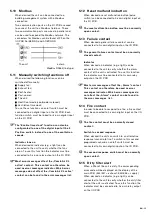
Two communication ports on the I/O PCB are used
to connect the unit to a Modbus field bus. These
two communication ports are wired in parallel and
can be used to expand the Modbus network. The
connectors for Modbus can be found at X9 on the
I/O PCB A6/B6/GND and A7/B7/GND.
The unit
extern
ModBus RS485 (line type)
5.11 Manually switching functions off
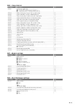
When desired the following functions can be
switched off manually:
�
Supply fan;
�
Exhaust fan;
�
Post-heater;
�
Post-cooler;
�
The unit;
�
Heat/Cool mode (coolmode is closed);
�
Ventilation time clock;
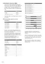
To use these functions an on/off switch must be
connected to an digital input on the I/O PCB. Each
function switch must be linked to its own digital input
on the I/O PCB.
The “Enable time clock” function can also be
configurated to one of the digital input of the 3
Position switch instead to one of the ventilation
speeds.
Indicator fans on
When desired an indicator (e.g. a light) can be
connected to the unit to verify whether the fans
are on. To use this function the indicator must be
connected to his own relay output on the I/O PCB.
Most error messages affect the „ComfoAir XL
active“ contact. This contact can therefore be
used as error messages indicator. Which error
messages do not affect the „ComfoAir XL active“
contact can be found in the error messages list.
5.12 Reset malfunction button
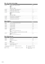
When desired a reset malfunction button (pulse
switch) can be connected to his own digital input on
the I/O PCB.
The reset malfunction button must be a normally
open contact.
5.13 Failure contact
When desired a general failure contact can be
connected to his own digital input on the I/O PCB.
The general failure contact must be an normally
closed contact.
Indicator
When desired an indicator (e.g. a light) can be
connected to the unit to verify whether the alarm
contact of the unit is activated. To use this function
the indicator must be connected to his own relay
output on the I/O PCB.
Most error messages affect the „Alarm“ contact.
This contact can therefore be used as error
messages indicator. Which error messages do
not affect the „Alarm“ contact can be found in
the error messages list.
5.14 Fire contact
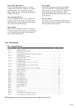
In order to be able to respond to a fire, a fire contact
must be connected to his own digital input on the I/O
PCB.
The fire contact must be a normally closed
contact.
Switch to second response
When desired the unit can switch to an alternative
response/scenario to fire. To switch to this second
programed scenario an on/off switch must be
connected to his own digital input on the I/O PCB.
The second response switch must be a normally
open contact.
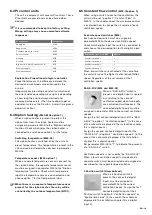
5.15 Dirty filter alert
When a filter of the unit is dirty, the corresponding
error code will be displayed on the display of the
main PCB. (E44/E47 = exhaust; E45/E48 = supply)
When desired an indicator (e.g. a light) can be
connected to the unit to verify whether the dirty filter
alert of the unit is activated. To use this function the
indicator must be connected to his own relay output
on the I/O PCB.
Содержание ComfoAir 1500
Страница 1: ...ComfoAir XL ComfoAir Eco Manual Cooling Fresh Air Clean Air Heating...
Страница 45: ...EN 45...
Страница 46: ...46 EN...
Страница 47: ...EN 47...


