14 - EN
5.5 Constant flow control
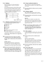
Separate speed switches
When the ventilation setting of the unit must be
controlled by constant flow connect up to 4 switches
to the digital inputs on the I/O PCB. Each switch
must be linked to its own digital input.
SAG 0-3 CV
The “SAG 0-3 CV” is a position
switch with 3 settings in one
switch. The “SAG 0-3CV” can also
be connected to the unit instead of
3 separate switches. This saves a
digital input by switching to the
second ventilation speed when two inputs are
controlled simultaneously. Connect the “SAG 0-3
CV” switch to the digital inputs 4 and 6 on the I/O
PCB as shown in the schematic.
Ventilation speed 4 is not used by the “SAG 0-3CV”.
When a fourth ventilation speed is also desired a
separate switch must be installed to his own digital
inputs on the I/O PCB.
3 Position switch (Umschaltend)
Connect the 3 Position switch
switch to the digital inputs 4, 5 and
6 on the I/O PCB as shown in the
schematic.
The “Enable time clock” function
can also be configurated to one of
the digital input of the 3 Position switch instead to
one of the ventilation speeds.
1
3
4
5
SAG 0-M
The SAG 0-M is a switch for
variable speed adjustment.
Connect the SAG 0-M to its own
analog input on the I/O PCB.
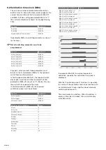
5.6 Sensor (0..10V) control
When the ventilation setting of the unit must be
controlled by sensors connect the desired sensors to
the analog inputs on the I/O PCB. Each sensor must
be linked to its own analog input.
5.7 Constant pressure control
When the ventilation setting of the unit must be
controlled by pressure sensors connect the desired
pressure sensors to the analog inputs on the I/O
PCB. Each pressure sensor must be linked to its own
analog input.
5.8 Switch to second setpoint
When the ventilation setting of the unit is controlled
by one or more sensors it is possible to select a
second setpoint. To use this function an on/off
switch must be connected to his own digital input on
the I/O PCB.
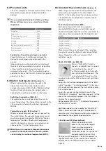
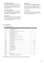
5.9 Summer night ventilation
When desired the unit can provide summer night
ventilation to lower the indoor temperature of the
building. To use this function an on/off switch must
be connected to his own digital input on the I/O PCB.
Indicator
When desired an indicator (e.g. a light) can be
connected to the unit to verify whether the summer
night ventilation is active. To use this function the
indicator must be connected to his own relay output
on the I/O PCB.
Содержание ComfoAir 1500
Страница 1: ...ComfoAir XL ComfoAir Eco Manual Cooling Fresh Air Clean Air Heating...
Страница 45: ...EN 45...
Страница 46: ...46 EN...
Страница 47: ...EN 47...


