background image

16 - EN

EN - 17

6. Commissioning

Each unit is preprogrammed with a set of default 
parameters. These preprogrammed settings are 
stored on the main PCB and can always be restored 
using parameter M99-99. Next to changing the 
preprogrammed parameters on the display it is also 
possible to load a new set of parameters to the 
main PCB. This can be done with the special control 
software “ComfoAir XL Control Center” or with 
parameter M90-03. 
More information about the “ComfoAir XL Control 
Center” can be found in its own manual. More 
information about parameter M90-03 can be found 
in the chapter about using de SD card on the main 
PCB.

Not all parameters can be set as default. Some 
parameter settings depend on the hardware which 
is installed on site. These parameters must be set 
to the correct value after installing. How to set the 
correct value can be found in this commissioning 
chapter.

After fitting and commissioning, a number of checks 
must be carried out. At the back of this document 
is an installation report stating the points requiring 
checking.

6.1 Air volume control (M02, M12-04)

The unit is preset with a set of air volumes for each 
ventilation level. These preset air volumes can be 
changed in parameter M02-01 till M02-08. 

Function

Parameter

Air volume Supply air 1

M02-01

Air volume Supply air 2

M02-02

Air volume Supply air 3

M02-03

Air volume Supply air 4

M02-04

Air volume Exhaust air 1

M02-05

Air volume Exhaust air 2

M02-06

Air volume Exhaust air 3

M02-07

Air volume Exhaust air 4

M02-08

 The unit is preset with a maximum air volume 

in parameter M04. These setting depend on 
the type of fans installed. Do not change these 
settings.

When two ventilation speeds are activated at the 
same time the unit will run on the highest activated 
ventilation speed. Regardless of the set volume of 
that ventilation speed.

In order to achieve a smooth control, it is 
recommended to program the ventilation levels in 
linear progression. If the ventilation levels are not 
programmed linearly, the fans might appear to be 
running uncontrolled or even power down when 
powering up was expected. 

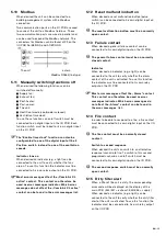
Positive sensor control

With a positive sensor control, power will go up if the 
measurement is below the set point. In the event of 
a higher measurement, power will go down. Most of 
the pressure sensors use positive control.

0–10 V signal  

Speed

Negative sensor control

With a negative sensor control, power will go up if 
the measurement is higher than the set point. In the 
event of a lower measurement, power will go down. 
Most of the CO2 sensors use negative control.

0-10 V signal 

Speed

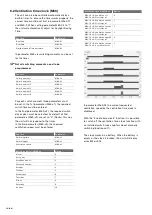
Balanced ventilation (M12-04)

When desired the unit can maintain balanced 
ventilation under all circumstances. Even when the 
software requires the reduction of only one fan. If 
the “balanced ventilation (frost)” option is activated 
in parameter M12-04 (option 1) all fans will always 
reduce or stop at the same time/rate. 

 The ComfoAir XL A is preset to balanced 

ventilation.

Содержание ComfoAir 1500

Страница 1: ...ComfoAir XL ComfoAir Eco Manual Cooling Fresh Air Clean Air Heating...

Страница 2: ...document Point of attention Risk of damage to the unit performance of the unit is compromised if instructions are not observed carefully Risk of personal injury for the user Maintenance Questions Plea...

Страница 3: ...Reset malfunction button 15 5 13 Failure contact 15 5 14 Fire contact 15 5 15 Dirty filter alert 15 5 16 External supply air temperature sensor 16 5 17 Battery 16 6 Commissioning 17 6 1 Air volume co...

Страница 4: ...gs 29 M13 Pre heater frost settings 30 M20 Failures 30 M50 Miscellaneous 30 M60 Time clock 31 M70 Filters 31 M80 Modbus Communication 32 M90 SD Card 32 M99 Service 32 7 Operation 33 7 1 Using the disp...

Страница 5: ...rcuit breaker can be locked with a padlock Always take ESD inhibiting measures when dealing with PCBs printed circuits boards such as wearing an antistatic wristband Store this document for the entire...

Страница 6: ...f the unit Suffixes between brackets mean there is space reserved for installing the specified function 3 Installation conditions In order to determine whether the unit can be installed in a certain a...

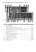
Страница 7: ...ir fan Down Extract air fan Standard H Drip tray with siphon underneath the plate exchanger Standard I Electronics panel with main PCB including integrated display Standard J Postheater for additional...

Страница 8: ...ated by a servomotor Standard F 2 drip catchers on the outdoor units Standard G 2 energy efficient EC motors with high efficient fan Top Outdoor air fan Down Extract air fan Standard H Drip tray with...

Страница 9: ...5 k 5 mA F 3 digital inputs Maximum terminal resistance detection closed 150 Maximum current 1 mA G Type B USB communications connector H 4 operating push buttons I LCD two line display J SD slot Che...

Страница 10: ...ree relay outputs D 6 digital inputs detection closed Maximum terminal resistance 150 Maximum current 1 mA E USB communications connector for linking to the main PCB F 2 communication ports G 3 analog...

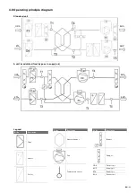
Страница 11: ...EHA SUP A unit modulated frost bypass in supply air ODA ETA EHA SUP Legend Code Decription Filter Heater Cooler Code Decription Heat exchanger Fan Temperature sensor Code Decription Bypass Damper ODA...

Страница 12: ...ETA EHA SUP Right hand version Legend Code Decription ODA Outdoor air SUP Supply air ETA Extract air EHA Exhaust air The following aspects must be taken into account while installing the air ducts In...

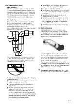
Страница 13: ...and closed for example The supplied overpressure siphon is suitable for overpressures of up to 600Pa in the cooling section The siphon with water lock must be fitted with a sealable filler opening and...

Страница 14: ...3 4 5 SAG 0 M The SAG 0 M is a switch for variable speed adjustment Connect the SAG 0 M to its own analog input on the I O PCB 5 6 Sensor 0 10V control When the ventilation setting of the unit must b...

Страница 15: ...esired a reset malfunction button pulse switch can be connected to his own digital input on the I O PCB The reset malfunction button must be a normally open contact 5 13 Failure contact When desired a...

Страница 16: ...king and maintenance process The battery connections must be counterflow connected to the airflow as indicated on the unit Cooler Heater Code Decription input output When connecting the battery the pi...

Страница 17: ...Air volume Exhaust air 1 M02 05 Air volume Exhaust air 2 M02 06 Air volume Exhaust air 3 M02 07 Air volume Exhaust air 4 M02 08 The unit is preset with a maximum air volume in parameter M04 These sett...

Страница 18: ...y the unit will not respond to the timer In the 3rd parameter M60 x3 the required ventilation speed must be entered Function Parameter Switching time M60 x1 Switching day M60 x2 Ventilation speed M60...

Страница 19: ...sing a switch to control the ventilation the unit must be set to option 0 Constant Flow in M02 10 In the chapter about the air volume control is explained how to change the air volume of each ventilat...

Страница 20: ...ratio factor must also be set in parameter M04 11 6 7 Constant pressure control M02 10 M04 11 M09 When using a pressure sensor to control the ventilation the unit must be set to option 1 Constant Pres...

Страница 21: ...y whether the fans are on the indicator must be assigned in parameter M06 to the ComfoAir XL active function Check which relay the indicator is connected to and choose option 8 for that relay indicato...

Страница 22: ...a maximum allowed pressure over the filter is set in parameter M70 13 When the set level is reached the unit will start powering down the corresponding fan to reduce the pressure and will display an...

Страница 23: ...ol When the supply temperature must be controlled by the outdoor temperature parameter M10 01 must be set to option 1 Outdoor heatline The desired heatline temperatures can be set in parameter M10 The...

Страница 24: ...when desired in parameter M12 When this frost protection is activated the unit will display error E43 and will power down or switch off the supply fan When the exhaust temperature drops below the set...

Страница 25: ...er determined which location setting is activated Never change the location settings of the pre heater 6 21 Parameters M1 Actual Controls Parameter Description Unit M01 01 Temperature NTC1 ODA outdoor...

Страница 26: ...10V supply air V M02 18 2nd setpoint 0 10V exhaust air V M02 19 Fire supply air 0 or 100 M02 20 Fire exhaust air 0 or 100 M02 21 Fire overrule supply air 0 or 100 M02 22 Fire overrule exhaust air 0 or...

Страница 27: ...t flow internal is selected at M2 10 6 Failure supply fan normal open 16 Enable post heater 7 Failure exhaust fan normal closed 17 Enable post cooler 26 Enable time clock 8 Failure exhaust fan normal...

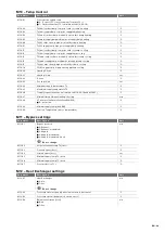
Страница 28: ...t change n a M08 02 Comport 25 Do not change n a M08 03 Comport 35 Do not change n a M08 04 Comport 45 Do not change n a M08 05 Comport 55 Do not change M80 11 Comport 1 control M80 12 Comport 2 contr...

Страница 29: ...eating P zone C M10 21 Heating I time sec M10 22 P zone C M10 23 Cooling I time sec M10 24 Minimum supply temperature T2 C M10 25 Maximum supply temperature T2 C M10 26 Tsupply request heatline calcul...

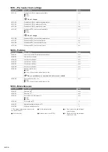
Страница 30: ...st reset failure n a M20 03 3rd last reset failure n a M20 04 4th last reset failure n a M20 05 5th last reset failure n a M20 06 6th last reset failure n a M20 98 Reset Actual Failure 0 No 1 Yes Yes...

Страница 31: ...ntspeed9 n a M60 61 Selectclock 6 Time min M60 62 Selectclock 6 Day8 n a M60 63 Selectclock 6 Ventspeed9 n a 8 The days can be set as follows 3 Weekend sat sun 7 Thursday 0 Never 4 Monday 8 Friday 1 E...

Страница 32: ...M90 SD Card Parameter Description Unit M90 01 Status 0 No card 1 Fail 2 5 Init 6 Ready 7 9 Writing n a M90 02 Save parameters on SD card 0 No 1 Yes n a M90 03 Restore parameters from SD card 0 No 1 Ye...

Страница 33: ...s a parameter follow this procedure 1 In the main page press the OK MENU UP DOWN button to show the first main parameter M01 ACTUAL CONTROLS M 2 Use the OK MENU UP DOWN or OK MENU UP DOWN button to se...

Страница 34: ...st data will be overwritten The main PCB writes data to the SD card at minute intervals The text SD then appears on the display In parameter M90 01 the status of the SD slot can be read out Function S...

Страница 35: ...nge clamp Do not forget to relock the hinges clamps after maintenance by turning locking screw back 90 The fans carry on rotating for a while after being switched off Always take ESD inhibiting measur...

Страница 36: ...ng the new filters into the unit Place the air direction arrow towards the plate exchanger Place the text Dust side away from the plate exchanger If the filter is in two sections the gap between them...

Страница 37: ...nd appropriately 8 4 Heat exchanger Inspect the heat exchanger once every 2 years 1 2 3 Open the fan maintenance access door Perform the following checks Contamination of plate exchanger Damage to pla...

Страница 38: ...rk is carried out by a registered installer The medium is a coolant that is contained in the cooling system under excess pressure Perform the following checks Check for corrosion and leakage Check for...

Страница 39: ...ailure in the stored parameter settings All parameters are set to default Check all parameters and adjust where necessary to comply with the required system settings E02 Internal failure Failure in th...

Страница 40: ...contact closed Frost risk The assigned digital temperature input contact Frost protection is activated Summer night cooling stops The supply fan is switched off The heating valve is set at a minimum o...

Страница 41: ...delivered products Liability The unit has been designed and manufactured for use in balanced ventilation systems incorporating Zehnder heat recovery systems Any other application is seen as inappropri...

Страница 42: ...tery or batteries are connected correct Check if the battery or batteries are not leaking Check the correct functioning of frost thermostat if present Check the bent fins of the drip catcher not shift...

Страница 43: ...rop damage and seal 12 months after installation Activity Y1 Y2 Y3 Y4 Y5 Y6 Y7 Checking panel filter pressure drop damage and seal Checking the draught excluders splitting Checking the servo motors of...

Страница 44: ...ure drop damage and seal 12 months after installation Activity Y8 Y9 Y10 Y11 Y12 Y13 Y14 Checking panel filter pressure drop damage and seal Checking the draught excluders splitting Checking the servo...

Страница 45: ...EN 45...

Страница 46: ...46 EN...

Страница 47: ...EN 47...

Страница 48: ...Luglio 6 Campogalliano MO 41011 T 39 059 978 62 00 F 39 059 978 62 01 info comfosystems it www comfosystems it Nederland The Netherlands Zehnder Group Nederland B V Lingenstraat 2 8028 PM Zwolle T 09...

Отзывы: