background image


User Manual 3PH HYD5000-HYD20000-ZSS 
Rev. 1.1 16/03/2021 

 
Identification: MD-AL-GI-00 
Rev. 1. of 16/03/2021 - Application: GID 


27/138 

4.2.


Connecting the battery 


!!!PLEASE NOTE!!! 

If the storage capacity needs to be increased by adding one or more batteries to an existing system, 
make sure that all the batteries (installed and to be installed) are fully charged. 
To check the charge status of each battery, connect them one at a time to the inverter and view the 
charge level on the display (all the instantaneous information can be accessed by pressing the “Down” 
key from the main menu). 
The batteries can be recharged from the excess photovoltaic production or by using the forced charge 
mode indicated in the “% charge mode” section of this manual. 
 

4.2.1.


Installing Pylontech batteries 


4.2.1.1.


Connecting a single battery tower 


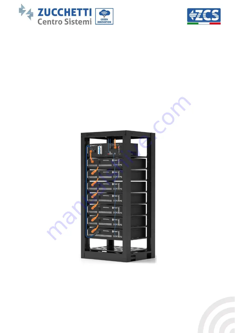
Figure 14 - Single battery tower 

Each tower of battery modules consists of a BMS connected in series to multiple battery modules. 
The devices to be used are: 


Содержание Azzurro 3PH HYD10000 ZSS

Страница 1: ...e no 9151 CNS0 IT 17778 Zucchetti Centro Sistemi S p A Green Innovation Division Via Lungarno 248 52028 Terranuova Bracciolini Arezzo Italy tel 39 055 91971 fax 39 055 9197515 innovation zcscompany com zcs pec it www zcsazzurro com Identification MD AL GI 00 Rev 1 1 of 16 03 2021 Application GID 3PH HYD5000 HYD20000 ZSS hybrid inverter User Manual ...

Страница 2: ...llation tools 18 3 5 Wall installation position 20 3 6 Assembly instructions 21 4 Electrical connections 22 4 1 Connection of protective ground cables PGND 25 4 2 Connecting the battery 27 4 2 1 Installing Pylontech batteries 27 4 2 1 1 Connecting a single battery tower 27 4 2 1 2 Installation with double battery tower 35 4 2 2 Installing WeCo batteries 39 4 2 2 1 Only one battery tower connected ...

Страница 3: ...rs 69 6 Buttons and indicator lights 71 7 Operation 72 7 1 Before configuration follow carefully 72 7 2 Commissioning 73 7 2 1 OSD language options 74 7 2 2 Setting of date and time confirmation 74 7 2 3 Importing of safety parameters 74 7 2 4 Setting of input channel 75 7 2 5 Setting of battery parameters 76 7 3 Main menu 77 7 3 1 Basic settings 80 7 3 2 Advanced settings 89 7 3 3 Event list 93 7...

Страница 4: ...1 Monitoring systems 111 11 1 External Wi Fi adapter 111 11 1 1 Installation 111 11 1 2 Configuration 112 11 1 3 Verification 121 11 1 4 Troubleshooting 123 11 2 Ethernet adapter 128 11 2 1 Installation 128 11 2 2 Verification 130 11 2 3 Troubleshooting 131 11 3 4G adapter 133 11 3 1 Installation 133 11 3 2 Verification 135 12 Warranty terms and conditions 138 ...

Страница 5: ...er or plant Copyright statement Copyright of this manual belongs to Zucchetti Centro Sistemi S p A No part of this manual including the software etc may be copied reproduced or distributed in any form or by any means without the permission of Zucchetti Centro Sistemi S p A All rights reserved ZCS reserves the right to final interpretation This manual is subject to change based on feedback from use...

Страница 6: ...o that it is accessible at all times Recipients This manual is intended for qualified technical personnel installers technicians electricians technical support personnel or anyone who is qualified and certified to operate a photovoltaic system who are responsible for installing and starting up the inverter in the photovoltaic and storage energy plant and for operators of photovoltaic and storage s...

Страница 7: ... system can be combined with WeCo or Pylontech batteries supplied in kit form by ZCS Azzurro The basic operating scheme is shown in Figure 1 the inverter has direct access to the photovoltaic production and to the management of the batteries so that they can be charged and discharged according to the current production needs and conditions and to the actual consumption It can also be connected to ...

Страница 8: ...arefully and make sure you fully understand its contents The 3PH HYD5000 HYD20000 ZSS inverter strictly complies with the safety regulations if it is installed connected and serviced according to the instructions in this manual During installation operation and maintenance all operators must follow the local safety guidelines Improper operation may result in electric discharges and or damage to pe...

Страница 9: ...electronic components against violent knocks humidity vibrations etc Zucchetti Centro Sistemi S p A shall NOT be responsible for any damage or loss caused by improper installation 2 2 Assembly and maintenance notes In case of maintenance or repair contact your service centre Contact your nearest distributor for information or assistance DO NOT repair the device yourself as this may cause injury or...

Страница 10: ...ce The inverters do not require any daily or periodic maintenance The heat exchangers and cooling fans must not be obstructed or clogged by dust dirt or other objects Before cleaning ensure that the DC switch is OFF the battery is switched OFF and the switch between the inverter and mains grid is OFF wait at least 5 minutes before cleaning To ensure good long term functioning make sure that there ...

Страница 11: ... and understand the content of the symbols before installing the inverter This symbol indicates a hazardous situation which if not avoided will result in injury Risk of electric shock wait at least 5 minutes before opening the cover of the 3PH HYD5000 HYD20000 ZSS inverter Beware of high voltage and electric shocks Beware of hot surfaces Complies with the European EC Conformity certification Groun...

Страница 12: ...the IEC 70 1 EN 60529 June 1997 standard Positive and negative polarities of DC voltage Photovoltaic and Battery This side up The 3PH HYD5000 HYD20000 ZSS inverter must always be transported handled and stored in such a way that the arrows are always pointing upwards Table 1 Symbols on the device 3 Installation The 3PH HYD5000 HYD20000 ZSS inverters are subjected to strict controls and inspection ...

Страница 13: ...rgy in excess and when the photovoltaic energy is lower than that required the inverter uses the energy stored in the battery to supply current to the local load 3 1 Product overview The 3PH HYD5000 HYD20000 ZSS storage inverters allow up to 10 overload to maximum power output and the Emergency Power Supply EPS mode can support inductive loads such as air conditioners or refrigerators with an auto...

Страница 14: ... 25A per string e Wide battery voltage range 200 700V f Off grid output can be connected to an unbalanced load g Multi parallel AC function more flexible solution h Intelligent monitoring RS485 Wi Fi Bluetooth GPRS Ethernet optional Figure 5 Inverter overview 1 Battery input terminals 7 DRMs active management of limitations 2 DC Switch 8 COM 3 PV input terminals 9 Port 1 for parallel connection 4 ...

Страница 15: ...03 2021 Application GID 15 138 3 2 Package contents No Part Qty 1 Inverter 1 2 Bracket 1 3 PV clamp terminals 4 4 PV clamp terminals 4 5 Metal clamp terminals fixed to PV input power cables 4 6 Metal clamp terminals fixed to PV input power cables 4 7 BAT clamp terminals 2 8 BAT clamp terminals 2 ...

Страница 16: ...AT input power cables 2 10 Metal clamp terminals fixed to BAT input power cables 2 11 M6 hexagonal screws 2 12 M8x80 expansion plugs to secure the bracket to the wall 4 13 AC Grid Connector 1 14 Critical load connector 1 15 Connection port connector for parallel function 2 16 8 pin terminal Matching terminal resistance parallel system 1pcs 17 DRMs connector 1 ...

Страница 17: ...rm 1 Table 3 Package contents 3 3 Requirements for the installation environment DO NOT install the 3PH HYD5000 HYD20000 ZSS on flammable material DO NOT install the 3PH HYD5000 HYD20000 ZSS in an area used for the storage of flammable or explosive materials Danger The casing and heat sink are very hot while the inverter is running therefore DO NOT install the 3PH HYD5000 HYD20000 ZSS in places whe...

Страница 18: ...s can be damaged during transport Therefore check the outer packaging before installation check that the materials are not damaged In case of damage contact the dealer as soon as possible It is recommended to remove the packing materials within 24 hours before installing the inverter 3 4 Installation tools No Tool Model Function 1 Drill recommended 6mm drill bit To make a hole in the wall 2 Screwd...

Страница 19: ...7 Crimping tool To crimp the power cables 8 Multi meter To meter the ground protection 9 Marker To mark the references 10 Tape measure To measure distances 11 Level To make sure the support is level and aligned correctly 12 ESD gloves For the operator s protection 13 Safety goggles For the operator s protection 14 Dust mask For the operator s protection Table 4 Installation tools ...

Страница 20: ...he area must be tidy and convenient for installation and well ventilated to prevent overheating DO NOT place it near flammable or explosive materials The AC overvoltage of the 3PH HYD5000 HYD20000 ZSS inverter belongs to Category III Maximum operating altitude 2000 m Ambient temperature range 25 C 60 C Relative humidity 0 100 non condensing Figure 6 Correct positioning of the inverter 1 Figure 7 C...

Страница 21: ... or paper under it to protect the housing Attention 1 Determine the position of the holes make sure the positions of the holes are level then mark them with a marker pen Use the drill to make the holes on the wall The drill must remain perpendicular to the wall Try not shake it while drilling the holes so as not to damage the wall If the holes are not level they must be repositioned and drilled ag...

Страница 22: ...he inverter must be installed and serviced by a professional electrician Wear protection equipment when working on high voltage high current systems such as inverters and battery systems Attention For the 3PH HYD5000 HYD20000 ZSS inverter the open circuit voltage Voc of the strings related to the modules connected in series must be 1000V Note The PV modules must have an IEC 61730 classification of...

Страница 23: ...SS Rev 1 1 16 03 2021 Identification MD AL GI 00 Rev 1 of 16 03 2021 Application GID 23 138 1 Direct insertion current sensors Figure 9 Configuration with CT current sensor 2 Meter CT sensor Figure 10 Configuration with meter CT sensor ...

Страница 24: ...ve electrode to the lithium battery connection of the positive electrode to the photovoltaic system Outdoor industrial cable for photovoltaic systems Conductor with cross section 6mm2 connection of the negative electrode to the photovoltaic system connection of the positive electrode to the photovoltaic system Outdoor industrial cable for photovoltaic systems Conductor with cross section 6mm2 conn...

Страница 25: ...ND The inverter does not have a transformer therefore the positive and negative polarities of the PV array do NOT have to be grounded All the metal parts in the photovoltaic supply system that do not carry current must be grounded e g PV module frame PV bracket dialler housing inverter housing Attention The PGND cables are pre set cables external power supply cables 4mm2 are recommended for ground...

Страница 26: ... crimped OT terminal insert the M5 screw and tighten the screw at a torque of 3Nm using the hex key NB L3 is the length between the insulating layer of the ground cable the L4 curved part and the core wires protruding from the secured part NB The cavity formed on the conductor just below the crimping strip must completely wrap the core wires which must be in contact with the terminal Figure 13 Ins...

Страница 27: ...ch battery connect them one at a time to the inverter and view the charge level on the display all the instantaneous information can be accessed by pressing the Down key from the main menu The batteries can be recharged from the excess photovoltaic production or by using the forced charge mode indicated in the charge mode section of this manual 4 2 1 Installing Pylontech batteries 4 2 1 1 Connecti...

Страница 28: ...ected in series via the cables shown in figure 4 The connection cables are supplied with the battery Figure 17 Power connector between battery modules The connector must be connected from the negative input of the first battery module to the positive input of the second one The negative input of the second battery module must then be connected to the positive input of the third module continuing t...

Страница 29: ...ollow the colour of the connector as a reference Figure 18 Power cable between battery modules Subsequently the external BMS must be connected to the series of battery modules Therefore the positive of the BMS must be connected to the positive of the first battery and the negative of the BMS to the negative of the last battery module the cables for this connection are supplied with the BMS Figure ...

Страница 30: ...plication GID 30 138 Figure 20 Power connection positive between the BMS and first battery module Figure 21 Power connection negative between the BMS and the last battery module Finally the BMS must be connected to the inverter via the power cables provided in the kit ZST CABLE KIT H as shown in the figure ...

Страница 31: ...38 Figure 22 BMS Inverter power cables left inverter side power terminals centre battery side power terminals left Figure 23 BMS power connection Negative cable connected to last battery module Positive cable connected to first battery module Positive cable connected to the inverter Negative cable connected to the inverter ...

Страница 32: ...e arranged as follows using the communication cables between battery modules Link port 1 of the BMS to link port 0 of the first battery Link port 1 of the first battery must be connected to link port 0 of the second Link port 1 of the second last battery must be connected to the last battery Figure 25 Communication connections the BMS and the first battery module left connection between the batter...

Страница 33: ...ing all the pins down this means the address equals 000000 Figure 27 000000 battery address For communication between the battery and inverter use the black communication cable supplied which has the BAT and INV labels on the RJ45 end On the BMS side insert the end labelled BAT in link port B The other end labelled INV must be cut leaving only the wires connected to pins 2 orange wire 4 blue wire ...

Страница 34: ...User Manual 3PH HYD5000 HYD20000 ZSS Rev 1 1 16 03 2021 Identification MD AL GI 00 Rev 1 of 16 03 2021 Application GID 34 138 Figure 28 CAN input of the BMS Figure 29 Pin Out CAN BMS input ...

Страница 35: ... battery modules and the BMS must be connected as indicated in section 2 1 1 As for the connection between each tower and the inverter the two power cables and coming from the BMS will be connected to the two inputs of the inverter BAT1 and BAT2 Figure 31 Inverter side DC power connection with two battery inputs populated Identify the two battery towers by assigning the number 1 to the tower conne...

Страница 36: ...must be connected to the last battery BMS Inverter communication The two BMS must be set with a different address by changing the position of the dip switches as shown below Address 000000 address 0 to be assigned to tower 1 Address 100001 address 1 to be assigned to tower 2 The RJ45 cable of the BMS with Address 1 tower 2 will depart from the link port B of the CAN RS485 input and connect to the ...

Страница 37: ...nication connector supplied with the inverter see figure 18 Connect the cable in position 5 white blue wire to position 8 of the communication connector supplied with the inverter see figure 18 Connect the cable in position 2 orange wire to position 9 of the communication connector supplied with the inverter see figure 18 Figure 33 Section of inverter connections Figure 34 COM port connection ...

Страница 38: ... of 16 03 2021 Application GID 38 138 PIN Invert er Battery communication Notes 7 CAN H blue wire Communication with the BMS of the lithium battery the CAN of the inverter adapts to the BMS of the lithium battery 8 CAN L white blue wire 9 GND S orange wire Figure 35 COM connection diagram ...

Страница 39: ...v 1 of 16 03 2021 Application GID 39 138 4 2 2 Installing WeCo batteries 4 2 2 1 Only one battery tower connected Figure 36 Single battery tower Each tower consists of a HV BOX connected in series to multiple battery modules The devices to be used are 1 external HV BOX Figure 37 HV BOX ...

Страница 40: ...ctor must be connected from the negative input of the first battery to the positive input of the second one From here the negative input must be connected to the positive input of the third module continuing the series until the negative input of the second last module is connected to the positive input of the last module In this configuration the positive input of the first module and the negativ...

Страница 41: ...ubsequently the HV BOX must be connected respecting the and polarity as it is powered by the batteries themselves Therefore the positive of the HV BOX must be connected to the positive of the first battery and the negative of the HV BOX to the negative of the last battery module The HV BOX must be grounded using the M5 screw terminals supplied First Battery Last Battery HV BOX ...

Страница 42: ...nnections between the HV BOX and the inverter the HV BOX module allows the connection of both channels coming from the inverter if properly set from the inverter LCD the battery column will be able to manage the maximum power of the inverter both when charging and discharging Figure 41 Inverter side DC power connection with two battery inputs populated CH1 Inverter CH2 Inverter ...

Страница 43: ... the second last battery to CAN A of the last battery LINK B of the second last battery to LINK A of the last battery As regards the positioning of the dip switches of the battery tower it is necessary to first check the serial number of the HV BOX module and select the address according to the following indications The DIP switches of all the battery modules except for the last one must be set so...

Страница 44: ...V BOX and first battery module connection between battery modules connection between second last and last battery module in the series HV BOX and Inverter communication Figure 43 HV BOX configuration In the case of a single battery tower the address must be set with all pins in the OFF position except for pin 7 which must be in the ON position Battery 1 Battery n ...

Страница 45: ...tery tower Power connections The power cables in each tower between the battery modules and HV BOX must be connected as indicated in section 2 1 1 As for the connection between each tower and the inverter the two power cables and coming from the HV BOX will be connected to the two inputs of the inverter BAT1 and BAT2 HV BOX 2 Battery 1 Battery Battery 1 Battery Battery n HV BOX 2 Battery n ...

Страница 46: ...o CAN A of the first battery LINK of the HV BOX to LINK A of the first battery CAN B of the first battery to CAN A of the second battery LINK B of the first battery to LINK A of the second battery CAN B of the second last battery to CAN A of the last battery LINK B of the second last battery to LINK A of the last battery HV BOX Inverter communication In the case of two battery towers 1 Battery Tow...

Страница 47: ... be connected by populating the CAN2 A input with the Inverter HV BOX communication cable The other end in which only the orange and white orange wires are present must be wired to the quick connect COM connector of the hybrid inverter as shown in the figures below The HV BOX must be grounded using the M5 screw terminals supplied Figure 53 Inverter HV BOX communication cable Figure 47 Section of i...

Страница 48: ...1 Application GID 48 138 Figure 48 COM port connection PIN Inverter Battery communication Notes 7 CAN H white orange wire Communication with thee HV BOX of the lithium battery the CAN of the inverter adapts to the HV BOX of the lithium battery 8 CAN L orange wire Figure 49 Description of COM interface ...

Страница 49: ...o Table 6 The steps are the same as for the battery Before removing the positive and negative connectors make sure that the DC circuit breaker is open Danger 4 4 Load connection Procedure 1 Select the type of cable and the appropriate specifications according to 2 Table 6 3 Pass the wire through the terminal Figure 50 Passing of the wire through the terminal 4 Connect the cable to the terminal acc...

Страница 50: ...erminal clamping 4 5 Grid connection The inverter is equipped with an integrated unit for monitoring the residual current when the inverter detects that the residual current exceeds 300mA the connection to the grid will be quickly disconnected Procedure 1 Select the type of cable and the appropriate specifications according to 2 Table 6 3 Pass the wire through the terminal Figure 53 Passing of the...

Страница 51: ... 03 2021 Application GID 51 138 4 Connect the wire to the terminal according to the identification on the terminal Figure 54 Connecting the wire to the terminal 5 Connect the terminal to the machine port and turn the clamp in a clockwise direction Figure 55 Connecting the terminal to the machine ...

Страница 52: ...lication GID 52 138 5 External communication 5 1 USB Wi Fi Figure 56 External Wi Fi connection Table 57 Interface description PIN Definition Function Notes 1 GND S Power Supply USB The USB power supply is 5V 1A It cannot be used to charge external devices 2 DP Data USB 3 DM Data USB 4 VBUS Power Supply USB ...

Страница 53: ...ble into the RJ45 connector The pins of the logical interface are defined according to the different standard requirements a Logical interface according to the VDE AR N 4105 standard 2018 11 necessary for controlling and or limiting the output power of the inverter The inverter can be connected to a RRCR Radio Control Receiver together with all the other inverters in the installation so as to dyna...

Страница 54: ...2 Input contact relay 2 K2 Output relay 2 3 L3 Input contact relay 3 K3 Output relay 3 4 L4 Input contact relay 4 K4 Output relay 4 5 NC Not connected Not connected 6 G GND Relay common node 7 NC Not connected Not connected 8 NC Not connected Not connected Table 7 Terminal description Table 8 Inverter preconfigured for the RRCR power levels 1 closed 0 open L1 L2 L3 L4 Active power Cos φ 1 0 0 0 0 ...

Страница 55: ...tput relay 1 2 NC Not connected Not connected 3 NC Not connected Not connected 4 NC Not connected Not connected 5 NC Not connected Not connected 6 G GND K1 Output relay 1 7 NC Not connected Not connected 8 NC Not connected Not connected Table 9 Terminal description L1 Active Power Power drop rate Cos φ 1 0 5 seconds 1 0 100 1 Table 10 Inverter preconfigured for the RRCR power levels 1 closed 0 ope...

Страница 56: ...on MD AL GI 00 Rev 1 of 16 03 2021 Application GID 56 138 5 3 COM Communication Multifunction Figure 61 COM interface Refer to Figure 6below for the RS485 connection if you want cascade monitoring of the inverters Figure 62 RS485 connection monitoring between inverters ...

Страница 57: ...ith BMS of the lithium battery 8 CAN0_L CAN negative polarity 9 GND S BMS communication GND 10 485TX0 RS485 differential signal 11 485TX0 RS485 differential signal 12 GND S GND signal Lead acid battery temperature measurement 13 BAT_Temp Lead acid battery temperature probe 14 DCT1 Dry Contact1 Option of the electric switch function 15 DCT2 Dry Contact2 16 VCC VCC communication 12V power supply Tab...

Страница 58: ... CT sensors for measuring the currents exchanged with the grid is shown in the figure below 5 4 1 Direct connection of CT sensors In the case of direct connection of the CT sensors use the dedicated connections supplied with the inverter as shown in the figure These sensors must be connected directly to the CT input of the inverter shown in the figure according to the indications in the table Figu...

Страница 59: ...ensors according to the direction on the sensor arrow Figure 65 Reference to sensor direction If it is necessary to extend the sensor connection cables use UTP network cables or FTP grid cables if there is electrical electronic noise near the wire that could cause interference This cable can be extended only up to a maximum of 50 metres Make sure to properly insulate the extension connections so a...

Страница 60: ...ary to use the Meter in addition to the sensors as shown in the figure Make sure to position the probes so that each toroid reads only the current flows relating to the exchange To do this it is recommended to position them at the output of the exchange meter Figure 67 Installation diagram of hybrid inverter with Meter on the exchange This involves connecting the sensors to the Meter and then conn...

Страница 61: ... terminals of the S phase sensor must be connected to PIN 4 red wire and PIN 6 black wire The terminals of the T phase sensor must be connected to PIN 7 red wire and PIN 9 black wire Position the sensors according to the direction on the sensor arrow ATTENTION hook the CT sensors to the phases only after they have been connected to the Meter Figure 69 Meter and sensors connections The connection b...

Страница 62: ...signal 24 Communication with Meters 6 RS485 differential signal 25 Table 13 Interface description Figure 71 Connection of Meter serial port NOTE For distances greater than 100 metres between the Meter and hybrid inverter it is recommended to connect two 120 Ohm resistors along the 485 daisy chain the first to the inverter between PINs 5 and 6 of the interface and the second directly to the Meter P...

Страница 63: ... to its inputs but also the power produced by external photovoltaic panels This is achieved by connecting a second Meter in a suitable position that allows reading the entire production of the photovoltaic system excluding that of the hybrid three phase inverter As for the RS485 communication Meter HYD all the meters present must be connected to the COM port of the inverter in inputs 5 and 6 of th...

Страница 64: ...evice in read mode on exchange enter the settings menu as shown below 1 Press SET and the word CODE will appear 2 Press SET again and the number 600 will appear 3 Enter the number 701 a From the first screen where the number 600 appears press the key once to write the number 601 b Press SET twice to move the cursor left highlighting 601 c Press the key once more to write the number 701 Note In cas...

Страница 65: ...e In case of error press SET until the number relating to thousands is highlighted and then press until only the number 1 appears at this point repeat the above procedure iii Press ESC to confirm and to scroll to the next setting b ADDRESS i Leave address 01 default setting so that the inverter assigns the data sent by the meter as the power relating to the exchange Configuring Meter on exchange a...

Страница 66: ...s indicated a CT i Press SET to enter the menu ii Write 40 1 From the first screen where the number 1 appears press the key several times to write the number 10 2 Press SET once to move the cursor left highlighting 10 3 Press the key several times to write the number 40 Note In case of error press SET until the number relating to thousands is highlighted and then press until only the number 1 appe...

Страница 67: ...voltaic production Switch on loads of more than 1 kW for each of the three phases of the system Stand in front of the meter and use the keys to scroll through the items and ESC to go back checking that 1 The Power Factor values for each phase Fa Fb and Fc phase shift between voltage and current are between 0 8 1 0 If the value is lower move the sensor to one of the other two phases until the value...

Страница 68: ...r value Pt is in line with the value shown on the inverter s display Checking the Meter on Production In case of meter on production repeat the above steps 1 Check the Power Factor as described in the previous case 2 The sign of the Pa Pb and Pc powers must match 3 Switch on the Inverter Hybrid and check that the total power value Pt is in line with the value shown on the inverter s display ...

Страница 69: ...Slave 1 Inverter Link port 0 of Slave 2 Inverter Link port 3 of Slave 2 Inverter Link port 0 of Slave 3 Inverter Link port 1 of Slave n 1 Inverter Link port 0 of Slave n Inverter 2 If the inverters connected are of the same size it is possible to connect in parallel the LOAD outputs in order to supply power to the same group of priority loads To do this a parallel switchboard must be used Make sur...

Страница 70: ...rs PIN Definition Function Notes 1 IN_SYN0 Signal synchronisation 0 The high signal level is 12 V 2 CANL CAN negative polarity 3 SYN_GND0 Signal synchronisation GND0 4 CANH CAN positive polarity 5 IN_SYN1 Signal synchronisation 1 6 SYN_GND1 Signal synchronisation GND1 7 SYN_GND2 Signal synchronisation GND2 8 IN_SYN2 Signal synchronisation 2 Table 14 Interface description ...

Страница 71: ...s Back to go back to the previous screen or enter the main page Up to move up the menu or for the 1 function Down to move down the menu or for the 1 function OK to select the current option of the menu or to move Table 15 Meaning of lights Status Connected to the grid Green light Off Grid Green light Alarm Red light Connected to the grid ON Standby connected to the grid Flashing Off Grid ON Standb...

Страница 72: ... inverter s LOAD port and the critical load with the automatic switch OFF 7 The communication cable of the lithium battery must be correctly connected 7 1 Before configuration follow carefully IMPORTANT Carefully follow this procedure to activate the inverter 1 Ensure that there is no power generation on the phases of the inverter 2 Set the DC switch to ON 3 Switch on the batteries a Pylontech Bat...

Страница 73: ...s renamed according to the country selected on the website download them to a USB stick and import them 4 Setting of input channel Default order BAT1 BAT2 PV1 PV2 5 Setting of battery parameters The default values are shown according to the input channel configured 6 The set up is completed Table 16 Parameters to be set for first start up NB Zucchetti Centro Sistemi S p A shall not be held respons...

Страница 74: ... the values on the USB stick beforehand To enable this option contact Zucchetti Centro Sistemi S p A Code Region Code Region 00 00 Germany VDE4105 18 00 EU EN50438 01 BDEW 01 EN50549 02 VDE0126 19 00 IEC EN61727 01 00 Italy CEI 021 Internal 20 00 Korea 01 CEI 016 Italy 21 00 Sweden 02 CEI 021 External 22 00 Europe General 03 CEI 021 In Areti 24 00 Cyprus 02 00 Australia 25 00 India 01 AU WA 26 00 ...

Страница 75: ...23 108 00 Lithuania Table 17 List of country codes 7 2 4 Setting of input channel Input Channel Config Input Channel1 Bat input 1 Up Down Bat input 2 OK Not use Input Channel2 Bat input 1 Up Down Bat input 2 OK Not use Input Channel3 PV input 1 Up Down PV input 2 OK Not use Input Channel4 PV input 1 Up Down PV input 2 OK Not used In the case of a single Pylontech battery tower set the inputs accor...

Страница 76: ...nput channel 3 PV input 1 Input channel 4 PV input 1 7 2 5 Setting of battery parameters Single Pylontech battery tower Single WeCo battery tower Double PYLON WECO battery tower Battery identification Battery 1 Battery 1 Battery 1 Battery 2 1 Battery Type PYLON WECO PYLON WECO PYLON WECO 2 Battery Address 00 00 00 01 3 Max Charge A 25 00 50 00 25 00 25 00 4 Max Discharge A 25 00 50 00 25 00 25 00 ...

Страница 77: ... Curve Scan Disable Logic interface Disable Table 18 Default values for other settings 7 3 Main menu Figure 78 Main menu interface From the main interface press the Down key to enter the page with the grid battery settings Main interface Down Grid Output Information Grid V R V Grid V S V Grid V T V AC Current R A AC Current S A ...

Страница 78: ...C Current T A Frequency Hz Battery Information 1 Batt1 V V Batt1 Curr A Batt1 Power KW Batt1 Temp Batt1 SOC Batt1 SOH Down Batt1 Cycles T Battery Information 2 Batt2 V V Batt2 Curr A Batt2 Power KW Batt2 Temp Batt2 SOC Batt2 SOH Batt2 Cycles T From the main interface press the Up key to enter the page with the photovoltaic settings ...

Страница 79: ...Up PV Information PV1 Voltage V PV1 Current A PV1 Power KW PV2 Voltage V PV2 Current A PV2 Power KW Inverter Temp From the main interface press the Back key to enter the main menu which has the following 5 options Main interface Back 1 System Settings 2 Advanced Settings 3 Energy Statistics 4 System Information 5 Event List 6 Software Update ...

Страница 80: ...6 Input Channel Config 7 EPS Mode 8 Communication Addr 9 Set ForceChargeTime 1 Language settings 1 Language Settings OK 1 中文 OK 2 English 3 Italian 4 2 Time Set the system time for the inverter 2 Time OK Time YYYY MM DD hh mm ss 3 Safety parameters The user can modify the safety parameters of the machine via a USB stick and must copy and modify the values on the USB stick beforehand To enable this...

Страница 81: ...ption kW with P 100W the inverter does not charge or discharge the battery Figure 85a If the PV generation kW consumption kW the power surplus is stored in the battery Figure 85b Figure 79 Inverter display in self consumption mode 1 If the PV generation kW consumption kW the battery is discharged to provide the necessary power until it is completely discharged Figure 86a If the battery is fully ch...

Страница 82: ...aic system cannot effectively charge the battery it may be necessary to set a date range for recharging the battery from the grid once this range has been set the inverter will operate in automatic mode for the remaining time Various settings can be made to manage the most complex requests 2 Time of use Mode OK Set Time of use Mode Rules 0 Enabled Disabled From To DOD Charge 02h00m 04h00m 070 0100...

Страница 83: ...ge Start 14 h 00 m Discharge End 16 h 00 m Discharge Power 02500 W Passive Use For more detailed information on passive operation please contact Zucchetti Centro Sistemi S p A 5 Self test 5 Autotest OK 1 Fast Self test 2 STD Self test The fast self test gives the same results as the STD standard self test but takes less time 1 Fast self test O K Start Self test Press Ok to start Testing 59 S1 Wait...

Страница 84: ...n MD AL GI 00 Rev 1 of 16 03 2021 Application GID 84 138 Wait Testing 27 S1 Wait Test 27 S1 OK Wait Testing 27 S2 Wait Test 27 S2 OK Wait Testing 81 S1 Wait Test 81 S1 OK Wait Testing 81 S2 Wait Test 81 S2 OK Wait Testing 81 S1 Wait Test 81 S1 OK Wait Testing 81 S2 Wait ...

Страница 85: ... Press Ok OK self test Press Down 59 S1 threshold 253V 900ms Press Down 59 S1 228V 902ms Press Down 59 S2 threshold 264 5V 200ms Press Down 59 S2 229V 204ms Press Down 27 S1 threshold 195 5V 400ms Press Down 27 S1 228V 408ms Press Down 27 S2 threshold 92V 200ms Press Down 27 S2 227V 205ms Press Down 81 S1 threshold 50 5Hz 100ms Press Down ...

Страница 86: ... 100ms Press Down 81 S2 49 9Hz 107ms Press Down 81 S1 threshold 49 5Hz 100ms Press Down 81 S1 50 0Hz 105ms Press Down 81 S2 threshold 47 5Hz 100ms Press Down 81 S2 50 1Hz 107ms 6 Configuration of input channel 6 Input Channel Config OK Input Channel Config Input Channel1 Battery input 1 Down OK Battery input 1 Disable Input Channel2 Battery input 2 Down Battery input 2 Disable ...

Страница 87: ...e OK 2 Disable EPS Mode If the PV generation kW consumption kW with P 100W the inverter charges the battery Figure 88a If the PV generation kW consumption kW the inverter does not charge or discharge the battery Figure 88b Figure 82 Display with EPS in operation 1 If the PV generation kW consumption kW with P 100W the inverter discharges the battery Figure 89a If the PV generation kW is normal but...

Страница 88: ...D AL GI 00 Rev 1 of 16 03 2021 Application GID 88 138 Figure 83 Display with EPS in operation 2 8 Communication address 8 Communication Addr OK 1 Communication Addr OK 2 Baud Rate OK 9 Setting of forced charge time 9 Set ForceChargeTime OK Charge Start OK Charge End OK a b ...

Страница 89: ...Curve Scan 5 DRM0 Control 6 Factory Reset 7 Parallel settings 8 Bluetooth Reset 9 CT Calibration 1 Battery parameters A Internal BMS 1 Battery Parameters OK 1 Battery Type 5 Max Charge A 2 Battery Capacity 6 Max Discharge A 3 Nominal Bat Voltage 7 Discharge Depth 4 Battery Cell Type 8 Save OK B Pylon Sofar WeCo External BMS 1 Battery Parameters OK 1 Battery Type 4 Max Discharge A 2 Battery Address...

Страница 90: ...of Discharge OK Depth of Discharge 50 EPS of Depth of Discharge 80 EPS Restore Depth 20 2 Battery active Function to be implemented 3 Anti Reflux The Anti Reflux Control mode can be enabled to limit the maximum power exported to the grid The power set is the maximum power to be fed into the grid 2 Anti Reflux OK 1 Anti Reflux Control OK Enable Disable 2 Reflux Power OK KW 4 IV Curve Scan The IV cu...

Страница 91: ...ble or disable logic interfaces Refer to the chapter on the connections between logic interfaces Section 5 page 52 4 Logic interface Control OK Enable OK Disable OK 6 Reset factory settings 5 Factory Reset OK 1 Clear Energy Data OK 2 Clear Events OK Delete the history of total power generated by the inverter 1 Clear Energy Data OK Enter password OK enter 0001 Delete history of errors recorded on t...

Страница 92: ...e the sensors have been connected the CT Calibration function in the advanced settings of the device can be used to allow the system to correctly read the current flows In order for the inverter to perform this operation it is necessary that The system is connected to the grid The batteries are present and switched on The loads in the system are off Photovoltaic production is off In this way the s...

Страница 93: ...ugh the main menu to monitor the details of the event history in real 3 Event List OK 1 Current Event List OK ID042 IsoFault 2 History Event List 2 History Event List OK 1 ID001 2020 4 3 14 11 45 OK 1 ID001 GridOVP 2 ID005 2020 4 3 11 26 38 2 ID005 GFCI 7 3 4 System interface information 4 System information OK 1 Inverter Info 2 Battery Info 3 Safety Param 1 Inverter Info OK Inverter Info 1 Produc...

Страница 94: ...o 2 Hardware Version Power Level Country Energy Storage Mode Down Inverter Info 3 Input Channel1 Input Channel2 Input Channel3 Input Channel4 Down Inverter Info 4 RS485 Address EPS Mode IV Curve Scan Anti Reflux Down Inverter Info 5 Logic interface Control PF Time Setting QV Time Setting Power Factor Down Inverter Info 6 Insulation resistance ...

Страница 95: ...ery Info OK Battery1 2 info 1 Battery Type Battery Capacity Depth of Discharge Max Charge A Down Inverter1 2 Info 2 Over V Protection Max Charge V Max Discharge A Min Discharge V Down Inverter1 2 Info 3 Low V Protection Nominal Bat Voltage 3 Safety Param OK Safety Param 1 OVP 1 OVP 2 UVP 1 UVP 2 Down Safety Param 2 OFP 1 OFP 2 UFP 1 ...

Страница 96: ... of 16 03 2021 Application GID 96 138 UFP 2 Down Safety Param 3 OVP 10mins 7 3 5 Energy statistics 3 Energy Statistics OK Today PV KWH Load KWH Export KWH Import KWH Charge KWH Discharge KWH Down Month PV KWH Load KWH Export KWH Import KWH Charge KWH Discharge KWH Down Year PV KWH Load KWH ...

Страница 97: ...KWH 7 3 6 Software Update The 3PH HYD5000 HYD20000 ZSS inverters offer the possibility to update the system via a USB stick for maximising the inverter s performance and preventing any operating errors caused by software bugs Procedure 1 Insert the USB stick into the inverter the files necessary for the update are already inside it 2 Open the DC switch 3 6 Software Update OK Enter password OK Ente...

Страница 98: ...upport service USB Fault MDSP File Error SDSP File Error ARM File Error Update DSP1 Fail Update DSP2 Fail Update ARM Fail Table 19 Software update errors 5 After completing the update close the DC switch wait for the LCD screen to turn off then restore the Wi Fi connection and open both the DC and AC switches wait a few seconds for the inverter to turn on again To check the current version of the ...

Страница 99: ...HYD5000 HYD20000 ZSS Rev 1 1 16 03 2021 Identification MD AL GI 00 Rev 1 of 16 03 2021 Application GID 99 138 8 Technical specifications 8 1 Technical data 3PH HYD5000 HYD8000 ZSS TECHNICAL DATA HYD5000 HYD6000 HYD8000 ...

Страница 100: ...anual 3PH HYD5000 HYD20000 ZSS Rev 1 1 16 03 2021 Identification MD AL GI 00 Rev 1 of 16 03 2021 Application GID 100 138 8 2 Technical data 3PH HYD10000 HYD20000 ZSS TECHNICAL DATA HYD10000 HYD15000 HYD20000 ...

Страница 101: ...User Manual 3PH HYD5000 HYD20000 ZSS Rev 1 1 16 03 2021 Identification MD AL GI 00 Rev 1 of 16 03 2021 Application GID 101 138 ...

Страница 102: ...th Are the input and output connections in good condition Are the configuration and settings correct for this type of installation Are the communication system and display free of damage If all these requirements are met proceed with the steps for viewing any errors Ground connection error The 3PH HYD5000 HYD20000 ZSS inverters comply with the IEC 62109 2 standard for earth alarm fault monitoring ...

Страница 103: ...fter obtaining the approval of the local grid operator ID003 GridOFP The grid frequency is too high ID004 GridUFP The grid frequency is too low ID005 GFCI Loss of charge Internal inverter errors Switch it off wait 5 minutes and switch it on again If the errors still occur contact technical support ID006 OVRT fault OVRT function error ID007 LVRT fault LVRT function in error ID008 IslandFault Isolat...

Страница 104: ...munication error AC ID035 SChip_Fault Chip error DC ID036 MChip_Fault Chip error AC ID037 HwAuxPowerFaul t Auxiliary power error ID041 RelayFail Relay detection error ID042 IsoFault Low impedance isolation Check the isolation resistance between the photovoltaic panels and the ground if there is a short circuit the error can be fixed immediately ID043 PEConnectFault Ground fault Check the Ac side o...

Страница 105: ... 2 ID059 TempFault_Inv1 Module 1 temperature protection ID060 TempFault_Inv2 Module 2 temperature protection ID061 TempFault_Inv3 Module 3 temperature protection ID065 VbusRmsUnbalanc e RMS bus voltage is not balanced Internal inverter errors Switch it off wait 5 minutes and switch it on again If the errors still occur contact technical support ID066 VbusInstantUnbal ance Transient voltage value o...

Страница 106: ...hnical support ID072 SwBusRmsOVP Software RMS overvoltage protection of the DC bus ID073 SwBusInstantOVP Software instantaneous overvoltage protection of the DC bus ID081 SwBatOCP Battery software overcurrent protection ID082 DciOCP Dci overcurrent protection ID083 SwOCPInstant Instantaneous output current protection ID084 SwBuckBoostOCP BuckBoost software flow ID085 SwAcRmsOCP Current actual valu...

Страница 107: ...ature limits and away from direct sunlight Check that the inverter has been installed according to the instructions in the manual ID114 FreqDerating AC frequency is too high Make sure that the grid frequency and voltage are within the acceptable range ID115 FreqLoading AC frequency is too low ID116 VoltDerating AC voltage is too high ID117 VoltLoading AC voltage is too low ID124 BatLowVoltageAla r...

Страница 108: ...unrecoverRelayFa il Permanent relay error ID141 unrecoverVbusUn balance Permanent unbalanced bus voltage error ID145 USBFault USB error Check the USB input of the inverter ID146 WifiFault WiFi error Check the Wi Fi input of the inverter ID147 BluetoothFault Bluetooth error Check the Bluetooth connection of the inverter ID148 RTCFault RTC clock error Internal inverter errors Switch it off wait 5 mi...

Страница 109: ...agging ID169 FanFault1 Fan1 error Check whether fan 1 of the inverter is working properly ID170 FanFault2 Fan2 error Check whether fan 2 of the inverter is working properly ID171 FanFault3 Fan3 error Check whether fan 3 of the inverter is working properly ID172 FanFault4 Fan4 error Check whether fan 4 of the inverter is working properly ID173 FanFault5 Fan5 error Check whether fan 5 of the inverte...

Страница 110: ...ween 25 and 60 C 10 4 Disposal Zucchetti Centro Sistemi S p a is not liable for the disposal of the equipment or parts thereof that does not take place according to the regulations and standards in force in the country of installation The symbol of the crossed out wheeled bin indicates that the equipment at the end of its useful life must be disposed of separately from household waste This product...

Страница 111: ...o monitor the inverter the RS485 communication address must be set to 01 directly from the display Installation tools Cross screwdriver External Wi Fi adapter 1 Switch off the inverter following the procedure described in this manual 2 Remove the cover for accessing the Wi Fi connector on the bottom of the inverter by unscrewing the two cross head screws a or by unscrewing the cover b as shown in ...

Страница 112: ... the Wi Fi modem Tools required for configuration Smartphone PC or tablet Go to front of the inverter and search for the Wi Fi network using a smartphone PC or tablet making sure that the signal from the home Wi Fi network reaches the place where the inverter is installed If the Wi Fi signal is present at the location where the inverter is installed the configuration procedure can begin If the Wi ...

Страница 113: ...ft and Android smartphone right Note Disconnect from any Wi Fi networks to which you are connected by removing automatic access Figure 87 Disabling automatic reconnection to a network 2 Connect to a Wi Fi network generated by the inverter s Wi Fi adapter i e AP_ where indicates the serial number of the Wi Fi adapter shown on the label of the device which operates as an access point ...

Страница 114: ...ndroid smartphone right 3 If you are using a second generation Wi Fi adapter you will be prompted for a password to connect to the inverter s Wi Fi network Use the password found on the box or on the Wi Fi adapter Figure 89 Password of external Wi Fi adapter Note To ensure that the adapter is connected to the PC or smartphone during the configuration procedure enable automatic reconnection of the ...

Страница 115: ... is not able to provide internet access confirm to maintain the Wi Fi connection even if the internet is not available Figure 91 Screen indicating that the Internet cannot be accessed 4 Open a browser Google Chrome Safari Firefox and enter the IP address 10 10 100 254 in the address bar at the top of the screen In the box that appears enter admin as both the Username and Password ...

Страница 116: ...n for accessing the web server to configure the Wi Fi adapter 5 The status screen will open showing the logger information such as the serial number and firmware version Check that the Inverter Information fields are filled in with the inverter information The language of the page can be changed using the command in the top right hand corner ...

Страница 117: ... left hand column 7 In the new screen that opens select the Wi Fi network to which you want to connect the Wi Fi adapter making sure that the Received Signal Strength Indicator RSSI is greater than 30 If the network is not visible press the Refresh button Note check that the signal strength is greater than 30 if not bring the router closer or install a repeater or signal amplifier Click Next ...

Страница 118: ... Fi network Wi Fi modem clicking on Show Password to make sure it is correct the password should not contain special characters and spaces Note During this step the system is not able to ensure that the password entered is the one actually requested by the modem therefore please make sure you enter the correct password Also check that the box below is set to Enable Then click Next and wait a few s...

Страница 119: ...tion MD AL GI 00 Rev 1 of 16 03 2021 Application GID 119 138 Figure 95 Screen for entering the password of the wireless network 2 9 Click Next again without ticking any of the options relating to the system security Figure 96 Screen for setting the security options 3 ...

Страница 120: ... configuration screen 4 11 At this point if the configuration of the adapter is successful the last configuration screen will appear and the telephone or PC will unpair from the inverter s Wi Fi network 12 Manually close the web page with the Close key on the PC por remove it from the background of the telephone Figure 98 Successful configuration screen ...

Страница 121: ...i Fi network in the list will confirm the successful configuration of the Wi Fi adapter Figure 99 Wi Fi network search on Smartphone iOS and Android Access point of the Wi Fi adapter is no longer visible If the Wi Fi network is still present in the list connect to it again and enter the status page Check the following information a Wireless STA mode i Router SSID Router name ii Signal Quality othe...

Страница 122: ...lashing on Figure 101 Initial status of LEDs 2 Final status NET left LED steady on COM central LED steady on READY right LED flashing on Figure 102 Final status of LEDs If the NET LED does not light up or if the Remote Server A option in the Status page still shows Not Connected the configuration was not successful i e the wrong router password was entered or the device was disconnected during con...

Страница 123: ...in The adapter can only be reset when the inverter is switched on Figure 103 Reset button on the Wi Fi adapter 11 1 4 Troubleshooting Status of LEDs present on the adapter 1 Irregular communication with inverter NET left LED steady on COM central LED off READY right LED flashing on Figure 104 Irregular communication status between inverter and Wi Fi Check the Modbus address set on the inverter Ent...

Страница 124: ... hand corner of the inverter s display steady or flashing Figure 105 Icons on the display of LITE single phase inverters left and three phase or hybrid inverters right Restart the adapter Press the reset button for 5 seconds and release After a few seconds the LEDs will turn off and will start to flash quickly The adapter will now be reset without having lost the configuration with the router 2 Ir...

Страница 125: ...that data between the router and server is not being transmitted correctly In this case it is advisable to carry out checks at the router level in order to ensure that there are no obstructions on the output of data packets to our server To make sure that the problem lies in the home router and to exclude problems with the Wi Fi adapter configure the adapter using the Wi Fi hotspot function on you...

Страница 126: ...ne connection verify that the 3G LTE network is active by going to Settings Mobile Phone and making sure that the Voice and data option is set to 5G 4G or 3G To enter the iOS settings menu click the grey gear icon on the home screen of your phone b Go to the Settings menu Personal Hotspot and turn on the Personal Hotspot option The hotspot is now enabled To change the password of the Wi Fi network...

Страница 127: ... choose the one activated by the smartphone and then enter the password associated with it which can be changed from the personal hotspot settings If at the end of configuration Connected appears next to Remote Server A then the problem is with the home router It is therefore advisable to check the brand and model of the home router you are trying to connect to the Wi Fi adapter some router brands...

Страница 128: ...communication address must be set to 01 directly from the display Installation tools Cross screwdriver Ethernet adapter Shielded network Cat 5 or Cat 6 crimped with RJ45 connectors 1 Switch off the inverter following the procedure described in this manual 2 Remove the cover for accessing the Wi Fi Eth connector on the bottom of the inverter by unscrewing the two cross head screws a or by unscrewin...

Страница 129: ...e inside the device 4 Connect the Ethernet adapter to the appropriate port making sure to follow the direction of the connection and ensure correct contact between the two parts a b Figure 111 Inserting and securing the ethernet adapter 5 Connect the other end of the network cable to the ETH output or equivalent of the modem or a suitable data transmission device ...

Страница 130: ...al 7 Unlike Wi Fi cards the Ethernet adapter does not need to be configured and starts transmitting data shortly after the inverter is switched on 11 2 2 Verification Wait two minutes after installing the adapter and check the status of the LEDs on the device Status of LEDs present on the adapter 1 Initial status NET left LED off COM central LED steady on SER right LED flashing on Figure 113 Initi...

Страница 131: ...n the adapter 1 Irregular communication with inverter NET left LED steady on COM central LED off SER right LED flashing on Figure 115 Irregular communication status between the inverter and adapter Check the Modbus address set on the inverter Enter the main menu with the ESC key first key on the left go to System Info and press ENTER to enter the submenu Scroll down to the Modbus address parameter...

Страница 132: ...tor is correctly crimped 2 Irregular communication with remote server NET left LED off COM central LED on SER right LED flashing on Figure 116 Irregular communication status between the adapter and remote server Check that the router has access to the network and that the connection is stable check that a PC can access the Internet Check that port 80 of the router is open and enabled to send data ...

Страница 133: ...set to 01 directly from the display 11 3 1 Installation Installation must be carried out for all inverters compatible with the adapter However the procedure is quicker and easier as there is no need to open the front cover of the inverter Installation tools Cross screwdriver 4G adapter 1 Switch off the inverter following the procedure described in this manual 2 Remove the cover for accessing the W...

Страница 134: ...ction of the connection and ensure correct contact between the two parts Secure the 4G adapter by tightening the two screws inside the package a b Figure 118 Inserting and securing the 4G adapter 4 Switch on the inverter by following the procedure described in the manual 5 Unlike Wi Fi cards the 4G adapter does not need to be configured and starts transmitting data shortly after the inverter is sw...

Страница 135: ...tatus of LEDs present on the adapter 1 Initial status NET left LED off COM central LED flashing on SER right LED flashing on Figure 119 Initial status of LEDs 2 Registration NET left LED flashes rapidly for about 50 seconds the registration process takes about 30 seconds COM central LED flashes rapidly 3 times after 50 seconds 3 Final status approx 150 seconds after the inverter has started NET le...

Страница 136: ...ss set on the inverter Enter the main menu with the ESC key first key on the left go to System Info and press ENTER to enter the submenu Scroll down to the Modbus address parameter and make sure it is set to 01 and in any case other than 00 If the value is not 01 go to Settings basic settings for hybrid inverters and enter the Modbus Address menu where the 01 value can be set Check that the 4G ada...

Страница 137: ...signal is present in the installation location the adapter uses the Vodafone network for 4G transmission if this network is not present or the signal is weak the SIM will use a different network or will limit the data transmission speed Ensure that the installation location is suitable for 4G signal transmission and that there are no obstacles that could affect data transmission Check the status o...

Страница 138: ...ntification MD AL GI 00 Rev 1 of 16 03 2021 Application GID 138 138 12 Warranty terms and conditions To view the Warranty Terms and Conditions offered by ZCS Azzurro please refer to the documentation inside the product box and on the website www zcsazzurro com ...

Отзывы: