Page 13
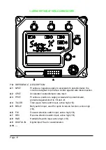
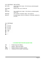
PIN REFERENCE DESCRIPTION
A11
NEB
electric brake driver output, 1.5A continuous, protected against
shortcircuits.
A12
NLED
Output to drive a led, 100mA max.
A13
---
A14
NMC
Line contactor driver output, 1.0A continuous, protected against
shortcircuit.
A15
PMC
Line contactor coil positive supply, 1.0A continuous.
A16
KEY
Controller supply, must be connected to +B through a cable and a
6.3A fuse.
PIN REFERENCE
B1
---
B2
NCLRXD
B3
PCLTXD
B4
NCLTXD
B5
GND
B6
+12
B7
---
B8
---
3.5 DESCRIPTION OF POWER CONNECTIONS
+B
=
Positive Supply from Battery.
-B
=
Negative Supply from Battery.
VMN
=
Negative Supply (via chopper) to Motor.
F1, F2
=
Connections to Drive Motor Field Winding.

