9
H. ZANDER GmbH & Co. KG • Am Gut Wolf 15 • 52070 Aachen • Germany
Tel +49 241 9105010 • Fax +49 241 91050138 • [email protected] • www.zander-aachen.de
P01
E61-456-00
Connection of
ZX20/21 family
Quick Start Guide
English Translation
Errors and technical changes reserved
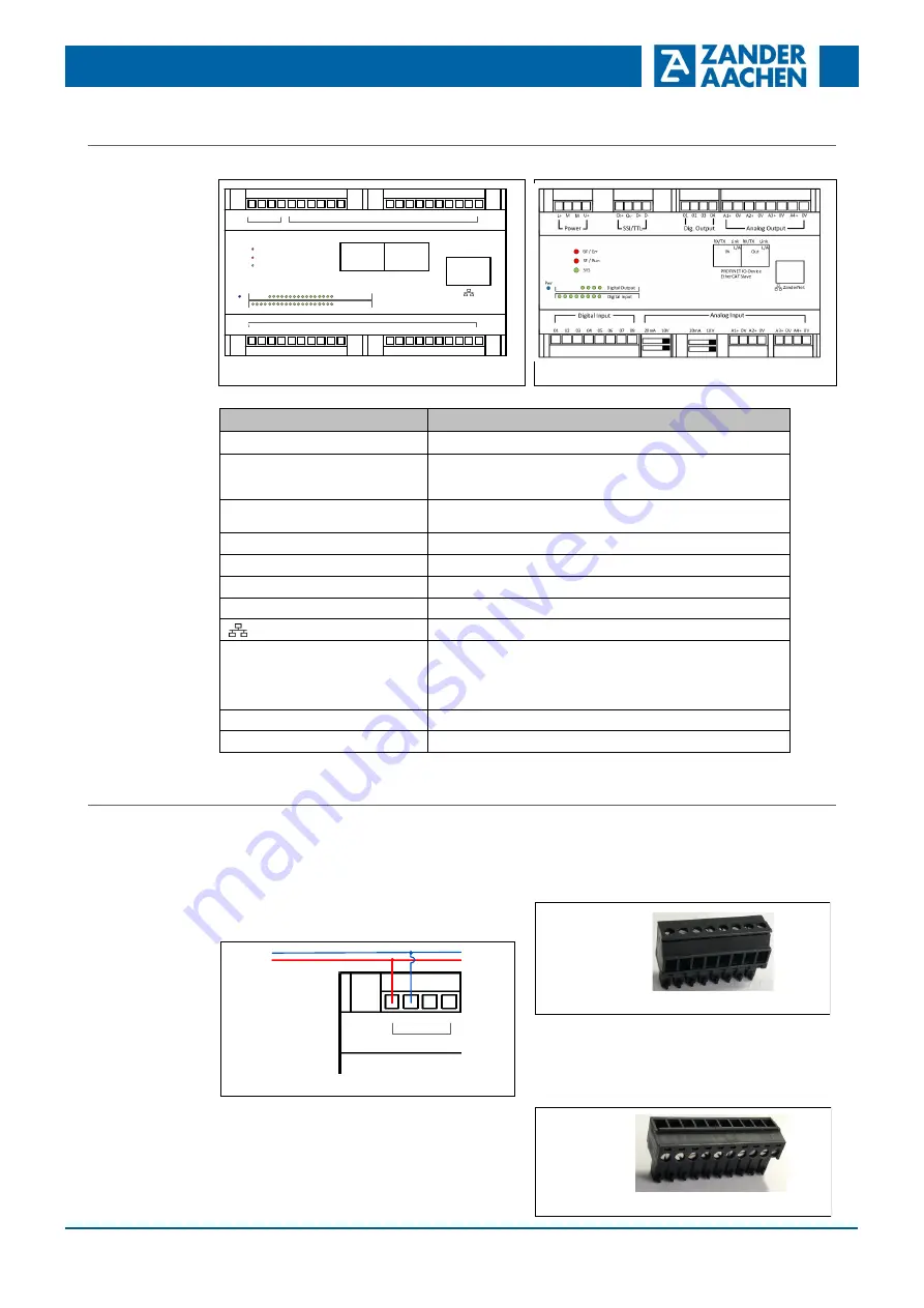
Quick Start Guide ZX-FPGA-PLC
Power supply
Connect the device according to the illustration.
Terminal
Description
L+
Positive supply voltage U
B
M (2 equivalent terminals)
0 V
-
Connection of the supply voltage and the voltage for the dig. Out-
puts and 0 V
-
potential for digital inputs. M and 0 V are internally
connected with each other
U+
Positive voltage for the dig. Outputs (may be different from operating
voltage L+)
Digital Input 01, 02, ...
Digital inputs
Digital Output 01, 02, ...
Digital inputs
Analog Input A
1
+ /
0 V, A
2
+ /0 V, ...
Analog voltage or current inputs (ZX21TPA and ZX21TCA only)
Analog Output A
1
+ /
0 V, A
2
+ /0 V, ...
Analog voltage outputs (ZX21TPA and ZX21TCA only)
Ethernet port
SSI/TTL
SSI or ZanderLink interface or TTL differential inputs or outputs
(ZX21TPA and ZX21TCA only). The interface can be used in the user
program for ZanderLink, SSI encoders or as inputs or outputs for
(LV)TTL differential signals (e.g. for connecting a suitable incremental
encoder).
PROFINET IO
-
Device
PROFINET interface (ZX21TP and ZX21TPA only)
EtherCAT Slave
EtherCAT interface (ZX21TC and ZX21TCA only)
ZX20T, ZX21TP/TC
108
ZX20T
ZX21TP/TC
BF / ERR
SF / RUN
SYS
Digital Input
01 02 03 04 05 06 07 08 09 10
11 12 13 14 15 16 17 18 19 20
U
Power
L M
M
Digital Output
01 02 03 04 05 06
07 08 09 10 11 12 13 14 15 16
PROFINET IO
-
Device
EtherCAT Slave
RX/TX
RX/TX
Link
Link
IN
OUT
L/A
L/A
Pwr
Digital Output
Digital Input
ZX21TPA/TCA
ZX21TP/TC
The controllers of the ZX21 family (ZX21TP, ZX21TC,
ZX21TPA, ZX21TCA) are delivered including plug
-
in termi-
nals with lateral cable outlets (see picture).
Plug-in terminal with lateral cable outlets
The controllers of the ZX09 and ZX20 family (ZX09,
ZX09A, ZX09D, ZX09E and ZX20T) are delivered including
plug
-
in terminals with upper cable outlets (see picture).
Terminal sets with lateral cable outlets are available as
accessories (see next page, "Accessories").
Plug-in terminal with upper cable outlets
Plug-in terminals
Connect the device to the supply voltage according to the
illustration.
Warning:
Do not connect terminal M with PE of the power supply, as
this can lead to massive EMC interference. For shielded
lines (e.g. lines for analog signals or RS
-
485 lines), use a
shield rail to connect the shield to PE with low resistance.
Connection of the power supply
U+
Power
L+
M
M
24 V
0 V


