202
JOHNSON CONTROLS
FORM 201.21-NM4 (1020)
202
JOHNSON CONTROLS
MICRO PANEL
VSD SAFETIES (FAULTS) (CON'T)
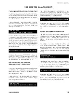
Low DC Bus Voltage (Software) fault
The low DC bus voltage trip level is set at 500 VDC. If
the DC bus drops below this level the unit/system will
fault and immediately shut down.
The low DC bus voltage cutout is an auto-restart safety
that will lock out on the 3rd fault in 90 minutes. The
fault is a unit fault for 3 compressor units. Below is an
example of the Status display fault message:
The low DC bus voltage cutout is a system fault (1/3
or 2/4) on 4 compressor units. Two key presses of the
STATUS key are required to show the fault on both
systems. Below is a sample Status display system fault
message:
SYS X YYYYYYYY LOW DC BUS VOLTAGE
UNIT YYYYYYYY
DC BUS VOLTAGE IMBALANCE
UNIT YYYYYYYY
LOW DC BUS VOLTAGE
X indicates the system and YYYYYYY indicates the
system is in a “FAULT” condition and will restart when
the fault clears or “LOCKOUT” and will not restart until
the operator clears the fault using the keypad.
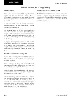
DC Bus Voltage Imbalance (Software) Fault
The 1/2 DC bus voltage magnitude must remain within
+/- 100 VDC of the total DC bus voltage divided by two.
If the 1/2 DC bus magnitude exceeds the +/- 100 VDC
tolerances, the unit/system will fault and immediately
shut down.
This safety will lock out on the 1st fault. The fault will
be a unit fault for 3 compressor units. Below is the
Status display fault message:
The fault will be a system 1/3 or 2/4 fault on 4 com-
pressor units. Two key presses of the STATUS key are
required to show the fault on both systems. Below is a
sample Status display fault message:
X indicates the system and YYYYYYY indicates the
system is in a “LOCKOUT” condition and will not
restart until the operator clears the fault using the key-
pad.
High Motor Current (Hardware) Fault
The three output lines to each phase of the compres-
sor motor are monitored via three current transformers
within the VSD. The unit’s three phases of instantaneous
output current will be compared to a predetermined
limit, which is contained in hardware. The nominal
peak current trip level is 575.5 Amps (554A min., 597A
max.). 380VAC, 60Hz and 400VAC, 50Hz nominal peak
current trip level is 649.5 Amps (626 Amps min., 674
Amps max.). The variation in trip point is the result of
component tolerances on the VSD Logic Board. If the
peak current limit is exceeded, the unit will fault and
shutdown immediately.
This fault is an auto-restart safety that will lock out
system on the 3rd fault in 90 minutes. The fault will
be an individual system/compressor fault for all units.
Following is a sample Status display fault message:
SYS X YYYYYYYY DC BUS VOLTAGE IMBALANCE
X indicates the system and YYYYYYY indicates the
system is in a “FAULT” condition and will restart or
“LOCKOUT” and will not restart until the operator
clears the fault using the keypad.
SYS X YYYYYYYY HIGH MOTOR CURRENT
Содержание YCAV1039
Страница 43: ...43 JOHNSON CONTROLS FORM 201 21 NM4 1020 43 JOHNSON CONTROLS 6 This page intentionally left blank ...
Страница 55: ...55 JOHNSON CONTROLS FORM 201 21 NM4 1020 55 JOHNSON CONTROLS 6 This page intentionally left blank ...
Страница 67: ...67 JOHNSON CONTROLS FORM 201 21 NM4 1020 67 JOHNSON CONTROLS 6 This page intentionally left blank ...
Страница 83: ...83 JOHNSON CONTROLS FORM 201 21 NM4 1020 83 JOHNSON CONTROLS 6 035 20890 009 REV LOCATION LABEL CON T LD11141 ...
Страница 229: ...229 JOHNSON CONTROLS FORM 201 21 NM4 1020 229 JOHNSON CONTROLS 8 This page intentionally left blank ...
Страница 249: ...249 JOHNSON CONTROLS FORM 201 21 NM4 1020 249 JOHNSON CONTROLS 8 This Page intentionally left blank ...
Страница 277: ...277 JOHNSON CONTROLS FORM 201 21 NM4 1020 277 JOHNSON CONTROLS 8 This page intentionally left blank ...
Страница 308: ...308 JOHNSON CONTROLS FORM 201 21 NM4 1020 308 JOHNSON CONTROLS MAINTENANCE NOTES ...
Страница 309: ...309 JOHNSON CONTROLS FORM 201 21 NM4 1020 309 JOHNSON CONTROLS 9 NOTES ...

