


64
YORK INTERNATIONAL
FORM 201.19-NM1 (204)
Technical Data
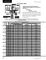
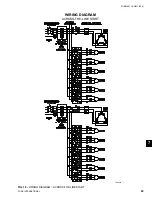
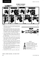
WIRING DIAGRAM
ACROSS-THE-LINE START
NOTES:
1. Field wiring to be in accordance with the current edi tion of
the National Electrical Code as well as all oth er ap pli ca ble
codes and speci
fi
cations.
2. Numbers along the right side of a diagram are line iden ti -
fi
ca tion numbers. The numbers at each line in di cate the line
number lo ca tion of relay contacts. An unlined contact loca-
tion signi
fi
es a nor mal ly closed contact. Numbers adjacent
to circuit lines are the cir cuit iden ti
fi
ca tion numbers.
3. Any customer supplied contacts must be suitable for
switching 24VDC. (Gold contacts rec om mend ed.) Con-
trol Wiring must not be run in the same conduit with any
line voltage wiring.
4. To cycle unit on and off automatically with contact
shown, install a cycling device in series with the
fl
ow
switch (FSLW). See Note 3 for contact rating and wiring
speci
fi
cations. Also refer to cau tions on page 67.
5. To stop unit (Emergency Stop) with contacts other than
those shown, install the stop contact between 5 and 1. If
a stop device is not installed, a jumper must be con nect ed
between ter mi nals 5 and 1. De vice must have a min i mum
contact rating of 100VA at 115 volts A.C.
6. Alarm contacts are for annunciating alarm/unit mal func -
tion. Con tacts are rated at 115V, 100VA, re sis tive load only,
and must be suppressed at load by user.
7. See Installation, Operation and Maintenance Man u al when
op tion al equipment is used.
8. Control panel to be securely connected to earth ground.
9. Use 2KVA transformer in optional transformer kit un less
there are optional oil separator sump heaters which ne ces -
si tates using a 3KVA transformer.
LEGEND
Transient Voltage Suppression
Terminal Block for Customer Connections
Terminal Block for Customer Low Voltage
(Class 2) Connections. See Note 2
Terminal Block for YORK Connections Only
Wiring and Components by YORK
Optional Equipment
Wiring and/or Components by Others
T S
FIG. 17
–
WIRING DIAGRAM – ACROSS-THE-LINE START
7.
LD09231
7.
LD09232
Содержание YCAS0130
Страница 45: ...45 YORK INTERNATIONAL FORM 201 19 NM1 204 5 This page intentionally left blank...
Страница 47: ...47 YORK INTERNATIONAL FORM 201 19 NM1 204 6 This page intentionally left blank...
Страница 63: ...63 YORK INTERNATIONAL FORM 201 19 NM1 204 This page intentionally left blank 7...
Страница 73: ...73 YORK INTERNATIONAL FORM 201 19 NM1 204 LD09239 FIG 22B CONTROL PANEL COMPONENT LOCATION 7...
Страница 75: ...75 YORK INTERNATIONAL FORM 201 19 NM1 204 7 LEGEND LD09241...
Страница 76: ...76 YORK INTERNATIONAL FORM 201 19 NM1 204 Technical Data LD03282 LD03283 2 ACE MOTOR PROTECTOR MODULE LD03284...
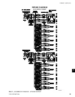
Страница 77: ...77 YORK INTERNATIONAL FORM 201 19 NM1 204 7 CONNECTION DIAGRAM SYSTEM WIRING LD09242...
Страница 78: ...78 YORK INTERNATIONAL FORM 201 19 NM1 204 Technical Data COMPRESSOR TERMINAL BOX LD09243...
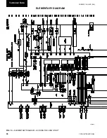
Страница 79: ...79 YORK INTERNATIONAL FORM 201 19 NM1 204 7 LD09373 ELEMENTARY DIAGRAM CONTROL CIRCUIT...
Страница 81: ...81 YORK INTERNATIONAL FORM 201 19 NM1 204 7 This page intentionally left blank...
Страница 113: ...113 YORK INTERNATIONAL FORM 201 19 NM1 204 COMPRESSOR COMPONENTS CONT D FIG 41 COMPRESSOR COMPONENTS LD03670 7...
Страница 121: ...121 YORK INTERNATIONAL FORM 201 19 NM1 204 7 This page intentionally left blank...
Страница 193: ...193 YORK INTERNATIONAL FORM 201 19 NM1 204 8 This page intentionally left blank...